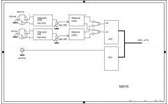
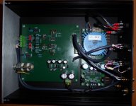
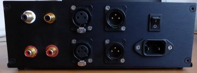
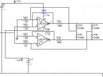
I was tired to solder divider diy patches every time I needed to measure power amplifiers with a soundcard, and also by investigating how to avoid groundloops and mains related interference spectral lines. So I decided to design and build a fully balanced universal analog interface that would change a soundcard to something that resembles an audio analyser like AP, or maybe rather like QA401. I started with using such thing a year and half ago and after getting good results, I decided to make a stand-alone instrument like this. The interface, called MSYS, has 2 channels, one for low level signals up to 4Vrms, second for high level signals up to 40Vrms (at least). The gain and sensitivity is controlled by DACT stepped attenuator. Block diagram is attached, circuit diagram is attached as well, and a photo of the instrument and its rear panel. The circuit uses OPA314, AD797, OPA627 and ADA4898 chips. Dynamic range is high, distortion very low and it makes a useful tool from a conventional soundcard. Balanced input is a must if we measure a power amplifier.
Attachments
I've found single ended connections fine for valve amps.Balanced input is a must if we measure a power amplifier.
Excellent design for the application. What I would really like is similar but with an AGC on the input with a level indicator. What would be fun is a motorized pot with a pointer dial showing the actual level at the input. . .
Thank you Demian, yes AGC would be a great feature. I am afraid I would not find enough courage and skills for such implementation, but maybe you are planning it for your QA analyzer?
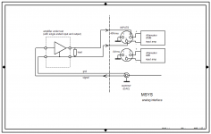
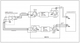
The attached image shows the MSYS analog interface used for measurement of a standard power amplifier with a single ended input and speaker output with one terminal at analog ground. No measuring ground loop is created, because of balanced input of the system.
The unused channel may serve as single ended to balanced converter, in case that the power amplifier has balanced input and soundcard used has only single ended output.
Rule of thumb: never create a loop from analog grounds, especially if one of the signals is single ended. Balanced inputs and outputs help to get rid of this common issue.
Attachments
All the sound cards i know of (including the RTX) share grounds between input and output. usually the differential input will address the ground loops but not always. Also when switching between single ended and balanced the level changes making for potential confusion (more than a few people have been confused by this on the RTX)
Below is a circuit that will create a 600 Ohm source and provide the same level for a balanced or single ended input. it will also isolate from ground loops. I lifted it from a Boonton analyzer which got it from an HP instrument. It works quite well as long as you don't exceed the peak limits. You can make a 50 Ohm version as well but the power dissipation goes up dramatically.
Below is a circuit that will create a 600 Ohm source and provide the same level for a balanced or single ended input. it will also isolate from ground loops. I lifted it from a Boonton analyzer which got it from an HP instrument. It works quite well as long as you don't exceed the peak limits. You can make a 50 Ohm version as well but the power dissipation goes up dramatically.
Attachments
Not a criticism of the design (thanks, Pavel, and Demian for your extra insight), but wouldn't battery power/floating the instrument make a good amount of sense to bypass some of these issues?
Battery is how Jan addressed his autoranger. Not sure how the different solutions compare performance wise.
All the sound cards i know of (including the RTX) share grounds between input and output.
Yes they do. However, it is possible to get rid of signal ground loop quite effectively by using only one reference ground. Attached is the schematic when I connect the MSYS interface to a soundcard which has only SE I/O. Second channel of the MSYS acts as a SE/bal converter to measure power amplifier with balanced I/O. SE out from the soundcard is connected to MSYS balanced input, no ground, just shielding. Reference ground is the output connection. No loop.
Attachments
Not a criticism of the design (thanks, Pavel, and Demian for your extra insight), but wouldn't battery power/floating the instrument make a good amount of sense to bypass some of these issues?
It would make a partial improvement. However, I want my system to work with 2 x 10m I/O cables and then any loop is to be avoided.
I get 115dBV(A) S/N (1V referred) at the balanced output. Max. output balanced voltage is 19V, so the full output S/N is 140dB, however this is unlikely to be utilized, as the soundcard input FS is usually 1-2V.
I've battery powered my soundcard, and have a battery powered USB isolator, and can use a laptop, as means to suppress mains borne earth loop currents from the amplifier-under-test's connection between ground and mains PE.
For valve amps I renovate I make an effort to link input and output grounds with minimum opportunity for noise insertion in that link within the amp.
Other practical issues that can degrade the noise floor, as others have noticed, is to be careful of nearby noise sources (such as bench lamps) and connecting other mains powered instruments to the DUT.
Just saying that with a bit of care, single-ended test setups for some applications can provide a noise floor well under the DUT noise floor.

- Home
- Design & Build
- Equipment & Tools
- Analog interface to get an audio analyser from a soundcard