Hi Alfred,how much would you be willing to pay for a loaded and tested board? (plus shipping)
Thanks for your offer. I recently made my own notch filter. Not as good as yours, but for now it will do.
I like to be able to repair what I own and SMD is not my thing (yet). I may build yours on day… I like it…
Regards, Gerrit
Hi all,
I think it is time to show you my latest project:
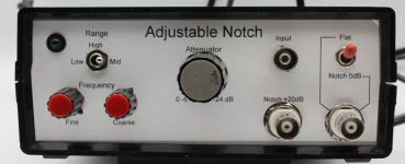
Audio Notch Filter with Adjustable Frequency.
It is described in ELEKTOR 9/2024.
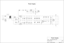
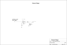
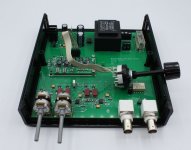
Please find attached the schematics, layout and some pictures.
The frequency can be modified in 3 ranges (High, mid, low) with two pots (fine and coarse)
Alfred
I think it is time to show you my latest project:
Audio Notch Filter with Adjustable Frequency.
It is described in ELEKTOR 9/2024.
Please find attached the schematics, layout and some pictures.
The frequency can be modified in 3 ranges (High, mid, low) with two pots (fine and coarse)
Alfred
Attachments


Hello Alfred
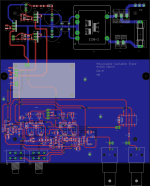
I read most of your articles about filtering in the Elektor Magazine. But 99% of my components are thruhole ( old school ) stuff an I make all my PCB´s the diy way. Thatswhy I decided to design an PCB with almost wired components, exept the OPA`s an some caps. The PCB is a 2 layer 100x160mm format layouted with an old Eagle version in a way to easy replicate it at home. I did a 2 channel version with switchable gain via relais and an additional low noise powersupply on this one PCB. Just because this format gives enough space to make a 2 channel version. The circuit is not tested yet but i like the members here to have a first impression of my work. Maybe "gerrittube" is interrested in my work.
I read most of your articles about filtering in the Elektor Magazine. But 99% of my components are thruhole ( old school ) stuff an I make all my PCB´s the diy way. Thatswhy I decided to design an PCB with almost wired components, exept the OPA`s an some caps. The PCB is a 2 layer 100x160mm format layouted with an old Eagle version in a way to easy replicate it at home. I did a 2 channel version with switchable gain via relais and an additional low noise powersupply on this one PCB. Just because this format gives enough space to make a 2 channel version. The circuit is not tested yet but i like the members here to have a first impression of my work. Maybe "gerrittube" is interrested in my work.
Attachments
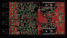
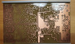
The PCB is ready for drilling now. I hope my layout reaches the low THD of the curcuit Alfred made. I had a earlier build of this filter but was not satisfied with the results. The housing should be a Fischer Elektronik KOH Case Type and the raw supply is external.
Attachments
Hello again
My build of Alfreds Dual Fliege Notch Filter ( https://www.diyaudio.com/community/...amps-attenuators-and-more.407815/post-7569519 ) is ready an the tests were prommising. But now i run into some problems that i don`t understand. When i mesure the 2 stages independently the results are as expected. But when i connect them together the attenuation for the 1kHz signal is not as good as with just a single one. The filter circuit itself is adjustable but i can`t get a better result as shown in the pictuers below.
My build of Alfreds Dual Fliege Notch Filter ( https://www.diyaudio.com/community/...amps-attenuators-and-more.407815/post-7569519 ) is ready an the tests were prommising. But now i run into some problems that i don`t understand. When i mesure the 2 stages independently the results are as expected. But when i connect them together the attenuation for the 1kHz signal is not as good as with just a single one. The filter circuit itself is adjustable but i can`t get a better result as shown in the pictuers below.
Attachments
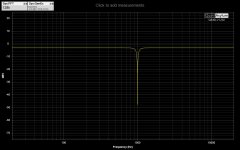

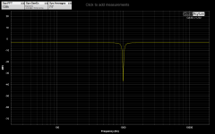

They are connected in series like in the schematic described here https://www.diyaudio.com/community/...amps-attenuators-and-more.407815/post-7569519
- Home
- Design & Build
- Equipment & Tools
- Analog Filters, Notches, Amps, Attenuators and more