Hi Brian,
the low pass (Sallen Key 8.order) or the bandpass (Sallen Key 4. order) (post #2) will improve the THD of your generator at 1 kHz.
The spectra are shown in post #15.
With the notch filter (post 4) you can extend the THD measurement range of your digitizer by 10 to 20 dB or even more.
For big input signals you need to reduce the level in front of the notch by an attenuator.
The UMC filters (extern and intern) remove the high frequency artefacts of the Generator of the Behringer since it does not have an internal filter.
Alfred
I do not know the Focusrite.These filters are very interessant, thank you for sharing.
I am collecting/building a measurement setup, i have a Focusrite Scarlett 2i2 3rd gen. and all components for an LA autoranger (waiting for me to solder it 🙂 ) - if i understand correctly, your filters would be able to improve this setup even further?
Would you please poste a screenshot of the spectrum of a loopback with 0 dBV and -10 dBV level. Sine 1 kHz
And a screenshot of the 1 kHz made with a scope.
I do not know the Focusrite.
Would you please poste a screenshot of the spectrum of a loopback with 0 dBV and -10 dBV level. Sine 1 kHz
And a screenshot of the 1 kHz made with a scope.
I am traveling at the moment, i will make those measurements as soon as i get home - thank you for responding 🙂
Thanks for sharing the filter designs.
According to the filter response for the BP filter, shown in post #1, the harmonics at 2 and 3 kHz should be attenuated by around 47 and 57dB respectively.
But the distortion at 2 kHz is almost unchanged compared to the generator signal of the AP555, shown in post #15. Perhaps a reduction of around 3dB with an input signal of 0dBV.
The level at 3 kHz seems to be reduced by around 15dB.
That points towards a relatively high distortion in the filter itself. Do you know if this is caused by the op-amps, capacitors, layout or resistors?
might be a mixture of all. The caps are very critical. You need to use COG types. One "X7R" or something will "destroy" the whole filter.
During the chip crisis OPA2210 were not available, so I used the good old NE5532. Depending on level, load and gain it is 10 to 20 dB worse.
Resistors are not that critical, but you should use thin film types.
During the chip crisis OPA2210 were not available, so I used the good old NE5532. Depending on level, load and gain it is 10 to 20 dB worse.
Resistors are not that critical, but you should use thin film types.
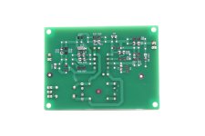
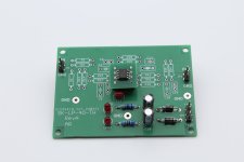
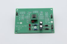
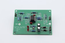
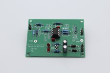
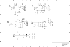
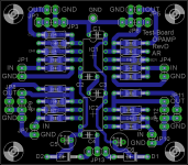
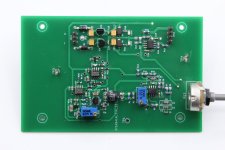
Just got the PCBs for my OpAmp test board. It helps to test different OPs in the same environment for THD and SNR.
Different gain and load.
DIL or SO8 on adapter.
Attached the schematics, layout and picture of the blank board.
Blank boards available.
Different gain and load.
DIL or SO8 on adapter.
Attached the schematics, layout and picture of the blank board.
Blank boards available.
Attachments
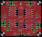
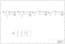
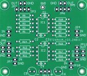
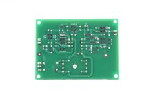
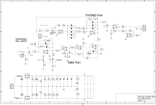
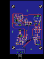
The latest PCB is a Sallen Key Low Pass filter forth order. In contrast to my other filter PCBs it can be loaded with through hole resistors on top or 1206 and 0603 SMD on the bottom side. Same is true for the caps. Please find attached the schematics, layout and some pictures. Some blank boards available.
Attachments
-
 IMG_2091.JPG155.8 KB · Views: 87
 -
 IMG_2090.JPG158.5 KB · Views: 66
 -
 IMG_2087.JPG179.9 KB · Views: 65
 -
 IMG_2086.JPG184.1 KB · Views: 66
 -
 IMG_2085.JPG186.5 KB · Views: 62
 -
 IMG_2084.JPG171.2 KB · Views: 71
 -
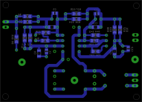 SK-LP-4O-TH_RevA-lay-bot.png21.3 KB · Views: 70
 -
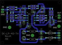 SK-LP-4O-TH_RevA-lay-top.png37.4 KB · Views: 94
 -
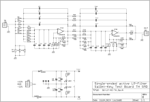 SK-LP-4O-TH_RevA-sch.png76.1 KB · Views: 104
See the latest Elektor issue to find my new "Analog 1 kHz Generator with low distortion":
https://www.elektormagazine.com/magazine/elektor-346/62910
Here are pictures of the schematics, layout, prototype and measurement.
https://www.elektormagazine.com/magazine/elektor-346/62910
Here are pictures of the schematics, layout, prototype and measurement.
Attachments


Hello,
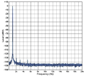
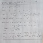
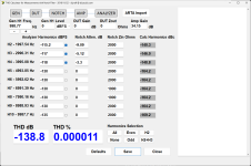
I tested the "Analog 1 kHz Oscillator with low distortion " from Alfred Rosenkraenzer. The output voltage of the oscillator was 3.171V RMS and the THD was measured with a passive Twin-T notch filter. The notch filter is followed by an amplifier with a gain of 51 (34.15dB). The output of the amplifier was connected to my audio analyzer R&S UPL. The FFT function gives the following values:
k2 (2kHz harmonic) = 5.5uV, k3 (3kHz harmonic) = 4.5uV, k4 (4kHzharmonic) = 4.0uV
THD von k2 is 5.5*10↑(-6)/(0.3511*51*3.171) = 9.686*10↑(-8) = -140.28dB.
THD von k3 is 4.5*10↑(-6)/(0.5547*51*3.171) = 5.016*10↑(-8) = -146.00dB.
THD von K4 is 4.0*10↑(-6)/(0.6839*51*3.171) = 3.617*10↑(-8) = -148.83dB.
The total THD is then
10*log(10↑(-14.028)+10↑(-14.600)+10↑(-14.883)) = -138.80dB.
That was the worst THD value I could measure. Often the harmonics have almost completely disappeared into the noise. Then the THD is below -140dB.
The Oscillator frequency is very stable and has not changed -998.77Hz-. The output voltage is also very stable.
I measured the THD+N with my UPL and it was -112dB. However, the board was not installed in a shielding housing. The THD+N value would then improve even further.
In summary I can say:
Inexpensive, good circuit with very good measurement results
Helmut Sell
Attachments


I wonder why you multiply the log function in your last calculation by 10 - you are dealing with voltages, not power.
To me, the THD based on your harmonic's RMS values would be:
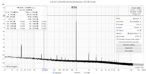
THD = 20*log(sqrt(5.5**2 + 4.5**2 + 4**2)*1e-6)/(51*3.171)) = -145.9dBc
This is the value I also measured with my build of the Janaczek oscillator coming from an open source project on GitHub:
https://github.com/mpinese/electronics-uldosc
Referring to the spectrum attached, the 2nd harmonic is at -96.7dBc, but since I used a notch filter and an LNA with 60dB gain, the true value is (-96.7 - 50) = -146.7dBc because my notch filter attenuates the 2nd harmonic by 10dB.
The other two harmonics have little influence on the THD, and can thus be ignored in the first approximation.
To me, the THD based on your harmonic's RMS values would be:
THD = 20*log(sqrt(5.5**2 + 4.5**2 + 4**2)*1e-6)/(51*3.171)) = -145.9dBc
This is the value I also measured with my build of the Janaczek oscillator coming from an open source project on GitHub:
https://github.com/mpinese/electronics-uldosc
Referring to the spectrum attached, the 2nd harmonic is at -96.7dBc, but since I used a notch filter and an LNA with 60dB gain, the true value is (-96.7 - 50) = -146.7dBc because my notch filter attenuates the 2nd harmonic by 10dB.
The other two harmonics have little influence on the THD, and can thus be ignored in the first approximation.
Attachments
Hello DNi,
When calculating the THD, you must take into account the values of the transfer function of the notch filter. These are :
0.3511 (-9.091dB) at 2kHz
0.5547 (-5.119dB) at 3kHz
0.6839 (-3.300dB) at 4kHz
You can't simply ignore the values for 3 and 4kHz .See THD calculation.
Helmut Sell
When calculating the THD, you must take into account the values of the transfer function of the notch filter. These are :
0.3511 (-9.091dB) at 2kHz
0.5547 (-5.119dB) at 3kHz
0.6839 (-3.300dB) at 4kHz
You can't simply ignore the values for 3 and 4kHz .See THD calculation.
Helmut Sell
Attachments
Hello Helmut,
Thank you for your explanation.
My mistake was that I assumed your harmonic's values in uV to have been already compensated for the notch filter attenuation.
Your THD calculation is then correct, although a little complicated for my taste.
BTW there is a neat THD calculation tool in this forum:
https://www.diyaudio.com/community/threads/low-distortion-audio-range-oscillator.205304/post-7018477
I applied it to your measurement, the result is in the attachment.
Re. neglecting the 3rd harmonic in my measurement results: the difference between the 2nd and 3rd harmonic is 10.7dB (notch filter att. taken into account), so the 3rd increases the THD by only 0.3dB, and the 4th has no practical effects.
I would expect a bit better performance from the oscillator you measured in comparison with my build because the PCB design forced me to use 0603 SMD parts throughout (except the capacitors, where I used Wima FKP2), which is suboptimal for measurement circuits.
Attachments
Hello DNi,
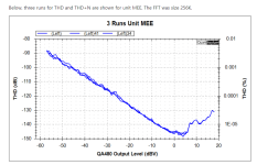
Thank you for your reply. I didn't develop this oscillator, I just measured it using my measuring capabilities. According to my information, QuantAsylum has also installed this topology in their QA480 1kHz oscillator. They also have a THD versus output level chart in their documentation. There you can see that the extremely low values of -145dB THD only exist at approx. 1-2V RMS. At 3V RMS, approximately -136dB to -138dB THD were measured here. This correlates quite well with my results. The amplitude control for this oscillator seems to be optimized for about 1V RMS. In the plot you can see that at approx. 7V RMS "only" -130dB THD was measured. However, an oscillator that can achieve a THD of almost -140dB at 3V RMS output voltage is definitely very good for me.
I can recommend this oscillator, especially because the component price is quite low.
Best regards
Helmut Sell
Attachments
Hi Alfred,
I appreciate very much what you publish here. My main problem is the SMD stuff, I need something with “normal“ components.
Perhaps I’l make my own PCB.
Regards, Gerrit
I appreciate very much what you publish here. My main problem is the SMD stuff, I need something with “normal“ components.
Perhaps I’l make my own PCB.
Regards, Gerrit
It very well worth getting up the learning curve with SMT, a cheap toaster oven can be converted, or simply a hot-air rework station. It can look daunting initially.
Hello DNI,Hello Helmut,
Thank you for your explanation.
My mistake was that I assumed your harmonic's values in uV to have been already compensated for the notch filter attenuation.
Your THD calculation is then correct, although a little complicated for my taste.
BTW there is a neat THD calculation tool in this forum:
https://www.diyaudio.com/community/threads/low-distortion-audio-range-oscillator.205304/post-7018477
I applied it to your measurement, the result is in the attachment.
Re. neglecting the 3rd harmonic in my measurement results: the difference between the 2nd and 3rd harmonic is 10.7dB (notch filter att. taken into account), so the 3rd increases the THD by only 0.3dB, and the 4th has no practical effects.
I would expect a bit better performance from the oscillator you measured in comparison with my build because the PCB design forced me to use 0603 SMD parts throughout (except the capacitors, where I used Wima FKP2), which is suboptimal for measurement circuits.
may I ask how do you measure THD. Which instrument (audio analyser)?
Alfred
Hi Gerrit,Hi Alfred,
I appreciate very much what you publish here. My main problem is the SMD stuff, I need something with “normal“ components.
Perhaps I’l make my own PCB.
Regards, Gerrit
how much would you be willing to pay for a loaded and tested board? (plus shipping)
Alfred
Hi,
for loading SMT parts you do not need more than a normal solder station with a small tip, a magnifier lamp and twizzers. (and not too much coffee)
And I am 66
Alfred
for loading SMT parts you do not need more than a normal solder station with a small tip, a magnifier lamp and twizzers. (and not too much coffee)
And I am 66
Alfred
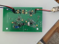
My setup consists of a 1kHz Victor oscillator with a parallel OPA1656 buffer, Hall topology notch filter with an input impedance of 1k8:Hello DNI,
may I ask how do you measure THD. Which instrument (audio analyser)?
Alfred
https://www.nanovolt.ch/resources/oscillators/pdf/passive_notch_filter_r1.pdf
which I modified to be adjustable by ±5Hz around the centre frequency.
The filter is followed by a 60dB LNA with the input noise density of 0.39nV/rtHz, also developed by Samuel Groner, see the article "A Low Noise Laboratory-Grade Measurement Preamplifier" at the link below
https://www.nanovolt.ch/publications/index.html
This system gives me a possibility to measure harmonics well below -150dBc.
- Home
- Design & Build
- Equipment & Tools
- Analog Filters, Notches, Amps, Attenuators and more