Hi all! My name is Alfred Rosenkraenzer, I am a retired analog design engineer with 36 years of experience. I was happy to work with instruments from Audio Precision in the company.
At home I own in the meantime a QA403, an old AP2422, a RME Babyface pro and a Behringer UMC202HD. Analog audio is my hobby.
I am giving lessons for design and testing analog filters at the DHBW in Germany. Three articles about filters are written by me for ELEKTOR.
My homepage is: www.alfredrosenkraenzer.de
I start this thread to share my work in the area of analog active filters like LP, HP, BP and Notches, Amps Attenuators etc. Some of these were published at ELEKTOR.
I made PCBs for it, if you are interessted just ask.
Here is a list of filters I did. The green marked are discussed in ELEKTOR:

I will start presenting some of my filters in detail.
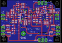
Most of my filters have the same size of 32 by 45 mm. Input connector is left, output on the right side. Power connections on all four sides. So it is easy to put them in series or in parallel for multi channel setups. There is also a voltage regulator board which can be stacked up on a filter.
This picture shows the dimensions:

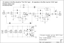
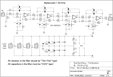
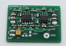
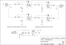
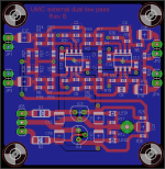
I did a Sallen Key low pass 8. order and a 4.order bandpass filter mainly to clean a 1 kHz test tone coming out of an audio interface. They were described in Elektor 5/2023.
Attached are pictures of the schematics, layouts, samples and measurements.
If you like to get more info, just ask!
Most of my filters have the same size of 32 by 45 mm. Input connector is left, output on the right side. Power connections on all four sides. So it is easy to put them in series or in parallel for multi channel setups. There is also a voltage regulator board which can be stacked up on a filter.
This picture shows the dimensions:
I did a Sallen Key low pass 8. order and a 4.order bandpass filter mainly to clean a 1 kHz test tone coming out of an audio interface. They were described in Elektor 5/2023.
Attached are pictures of the schematics, layouts, samples and measurements.
If you like to get more info, just ask!
Attachments
-
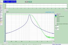 Bild_1_LP_8O-BP_4O.jpg118.5 KB · Views: 235
 -
 IMG_1013.JPG335.9 KB · Views: 290
 -
 SK-BP-4O_RevB_SW.png13.8 KB · Views: 303
 -
 SK-BP-4O_RevB_Lay.png25.9 KB · Views: 290
 -
 SK-LP-8O-Butt-1280-RevB-sch.png14.3 KB · Views: 251
 -
 SK-LP-8O-Butt-1280-RevB-lay.png18 KB · Views: 239
 -
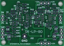 SK-LP-8O.jpg57.5 KB · Views: 200
 -
 IMG_0568f.jpg327.7 KB · Views: 210
Here comes the voltage regulator board:
Schematics:

And layout:

The next picture shows a filter on top of the regulator board.

and the loaded baoard:

Schematics:
And layout:
The next picture shows a filter on top of the regulator board.
and the loaded baoard:
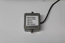
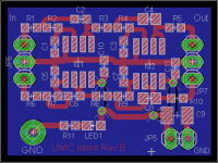
Now I like to talk about my Dual Fliege Notch Filter. There is an article about it in ELEKTOR September 2022.
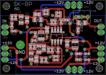
Here is the schematics and layout.

Layout:

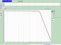
The frequency response:

and a zoom out:

More pictures attached.
Here is the schematics and layout.
Layout:
The frequency response:
and a zoom out:
More pictures attached.
Attachments
Very recently I came up with something extremely similar and shared this as well.
I personally think there is definitely still a place for analog active filters.
Either from a budget perspective or for those who want much better performance compared to most ADC's.
Especially looking at price performance ratio.
Unfortunately there was very little interest.
Guess it's not cool enough and to much work to solder and calculate a few parts?
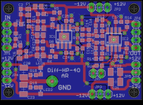
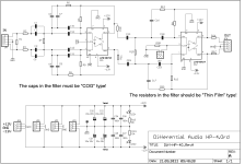
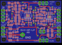
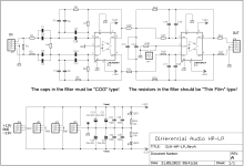
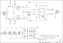
Today I will show my fully differential filters. I did 4.order low pass, high pass and a combination of low and high pass.
Finally a board with high impedance input and a 2. order low pass. At the final stage a common mode voltage can be added.
Here is a schematics:

And the layout:

All boards have the same size.
Finally a board with high impedance input and a 2. order low pass. At the final stage a common mode voltage can be added.
Here is a schematics:
And the layout:
All boards have the same size.
Attachments

What's the thought behind fully differential filters except for the input stage for an ADC or (maybe) output stage for a DAC?
Maybe as a single pre-stage for a fully balanced power amplifier with a bridged output (= also balanced).
Within a circuit itself the common mode noise is basically none existing?
Or very easy to mitigate.
Which is basically the only reason to go for differential signals.
Maybe as a single pre-stage for a fully balanced power amplifier with a bridged output (= also balanced).
Within a circuit itself the common mode noise is basically none existing?
Or very easy to mitigate.
Which is basically the only reason to go for differential signals.
Let's assume an instrument with differential inputs and a differential ADC at the end of the signal chain.
And a filter in between (for whatever reason).
If you change to a single ended filter after the input stage and then again to differential for the ADC you need a factor of 2 more gain
since you are not using the second output of the input stage (assuming it is differential).
This might lead to more THD and also SNR might be worse compared to a fully differential chain.
Re: post 2 8th order Butterworth. Parallel R and C with no value shown: Are these parts do not stuff?
you can tell the filter SW to use ESeries cap values, but the real caps normally have 5% tolerance or even more.
With the second cap in parallel you can compensate it. The higher the order of the filter the more sensitve it is to value variations.
It is a good idea to measure the caps values before you load them.
With the second cap in parallel you can compensate it. The higher the order of the filter the more sensitve it is to value variations.
It is a good idea to measure the caps values before you load them.
Hi b_force,Very recently I came up with something extremely similar and shared this as well.
I personally think there is definitely still a place for analog active filters.
Either from a budget perspective or for those who want much better performance compared to most ADC's.
Especially looking at price performance ratio.
Unfortunately there was very little interest.
Guess it's not cool enough and to much work to solder and calculate a few parts?
where can I find your filters?
Alfred
On the diff-to-se side you half the gain, so it kinda crosses out with each other.Let's assume an instrument with differential inputs and a differential ADC at the end of the signal chain.
And a filter in between (for whatever reason).
If you change to a single ended filter after the input stage and then again to differential for the ADC you need a factor of 2 more gain
since you are not using the second output of the input stage (assuming it is differential).
This might lead to more THD and also SNR might be worse compared to a fully differential chain.
(especially the SNR).
If it's just one simple (or maybe two) stage, I agree that it might not be worth the trouble.
But in a sense of an entire (crossover) filter, it's just not worth all the trouble (and additional costs)
Yes, I have quite some measurements. You can read the whole story in Elektor 5/2023. But you need to invest "fistfull euros". Please understand that I am not allowed to share the article.@alfredr Makes total sense, thank you. Interesting circuits. Have you measured distortion/noise, particularly for the post 2 circuits?
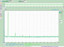
Some time ago I was lucky to get acces to an APx555, the best instrument money can buy.
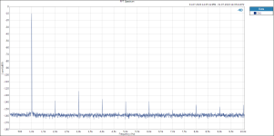
Here is a loopback of the digital (DAC) generator and the digitizer of the APx555 at 0dBV, not filter.
You can see quite some harmonics.
Now with the SK-LP-8.order with OPA2209 OpAmps. Not that bad, or?
Most of the harmonics disappeared. One left at 2 kHz and -130 dBc. There is some additional noise around 1kHz, but this is according the simulation.
At -10dBV level it looks like this.
During the chip crisis the OPA22xx were not available, so I started with the good old NE5532. Here a picture with 0 dBV level.
The second harmonic is about 10 dB higher.
Pictures of the band pass will follow.
Attachments
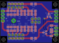
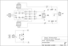
Today I like to show my attenuantor boards:

This is the manuell version. Two times single ended (stereo) or one times differential.

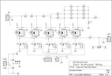
This is the single ended version using relay to switch. Can be controlled by a rotary switch or a controller (Arduino, ESP etc)

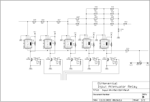
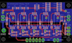
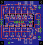
Now the differential one with relay.

This is how the SE relay attenuator may be connected to my dual fliege notch. The voltage regulator board is under the notch.

Finally the differential version. From left the diff attenuator, fully differential amp, dual notch filter. Above the amp is the voltage regulator.
Put it in a box with some switches and connectors and you get a nice instrument.
If you like to get some blank boards, just ask.
Attached the schematics and layouts of the attenuator.
If you have questions, just ask.
Alfred
This is the manuell version. Two times single ended (stereo) or one times differential.
This is the single ended version using relay to switch. Can be controlled by a rotary switch or a controller (Arduino, ESP etc)
Now the differential one with relay.
This is how the SE relay attenuator may be connected to my dual fliege notch. The voltage regulator board is under the notch.
Finally the differential version. From left the diff attenuator, fully differential amp, dual notch filter. Above the amp is the voltage regulator.
Put it in a box with some switches and connectors and you get a nice instrument.
If you like to get some blank boards, just ask.
Attached the schematics and layouts of the attenuator.
If you have questions, just ask.
Alfred
Attachments
-
 Input-Att-Rel-Diff-RevA-sch2.png10.5 KB · Views: 168
 -
 SE-Att-Relay-Lay.png20.5 KB · Views: 142
 -
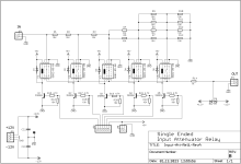 SE-Att-Relay-sch.png12.2 KB · Views: 139
 -
 Input-Att-RevB-lay.png17.6 KB · Views: 140
 -
 Input-Att-RevB-Sch.png8.8 KB · Views: 131
 -
 Input-Att-Rel-Diff-RevA-sch1.png13.1 KB · Views: 144
 -
 Input-Att-Rel-Diff-RevA-lay.png38.6 KB · Views: 136
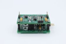
I also did a filter to be build into a Behringer UMC202HD. (or other audio interfaces)
It uses the +5 V power supply of the Behringer.
Here is a picture of such a filter inside the UMC:


Schematics and layout attached.
It uses the +5 V power supply of the Behringer.
Here is a picture of such a filter inside the UMC:
Schematics and layout attached.
Attachments
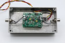
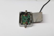
If you do not like to open and modify your Audio Interface I did a dual external low pass filter with voltage regulator on board.
It fits in a alu box from hammond. Power supply is +-15 V.


Attached are the schematics and the layout.
That's it for now. More to come in the future!
I have blank boards for most of the filters left in case someone is interested.
It fits in a alu box from hammond. Power supply is +-15 V.
Attached are the schematics and the layout.
That's it for now. More to come in the future!
I have blank boards for most of the filters left in case someone is interested.
Attachments

These filters are very interessant, thank you for sharing.
I am collecting/building a measurement setup, i have a Focusrite Scarlett 2i2 3rd gen. and all components for an LA autoranger (waiting for me to solder it 🙂 ) - if i understand correctly, your filters would be able to improve this setup even further?
I am collecting/building a measurement setup, i have a Focusrite Scarlett 2i2 3rd gen. and all components for an LA autoranger (waiting for me to solder it 🙂 ) - if i understand correctly, your filters would be able to improve this setup even further?
- Home
- Design & Build
- Equipment & Tools
- Analog Filters, Notches, Amps, Attenuators and more