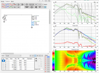
The hornresp exported phase data seems to be included in VCAD, then we should not flip the phase. Not sure what was the "measurement direction" for the output 2 though. Well, I've included the VCAD project here if anyone wants to play withit, I hope this is ok?
Edit. Found Hornresp thread that Phase window will show each output polarity and in this case its negative already. Not sure still whats the assumed physical location / orientation of the TL port.
View attachment 1098287
Found more data on this https://www.diyaudio.com/community/threads/hornresp.119854/post-6069923
There is path length setting somewhere in hornresp which I guess affects the combined output in hornresp. Output 1 and 2 on other hand seem to be point sources 1 meter away from observation point no matter what. I think if the output 2 polarity is indicated to be reversed it should be reversed back in VCAD, we want actual "measured" phase.
Also, hornresp exports power response, which is not same as axial response. I'm not sure how this affects things, probably some if "box" size falls within pass band of the device. Thinking of it, perhaps it works just fine to indicate results to about transducer sized wavelengths.
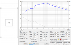
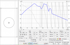
In which case setup in VCAD should work fine like so. If it was assumed 40cm deep box, TL somehow folder in and its output middle of the back:


Last edited: