
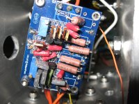
His amp had no ground from the amplifier PCB to ground. It would only ground through the source.
He added the missing wires.
He added the missing wires.
okei🙂 thats good🙂 everything under 100mV is okei. all under 10mV is good. all under 5mV is exelent🙂
I set up the 3 meters today...it appears there is no voltage at all. The power supply seems to work. what is the best way to move forward. What should I be checking ...first. I have worked with tubes however I have no idea where to begin. Could some of the transisters be backwards? ...or the the power mosfets. is there some order for troubleshooting. Thanks for any help.
Just to verify a few things-
Your PSU is measuring correctly?
Your meters are on DC volts?
You a meter across R11, another across R12, and one on the outputs?
If the PSU is good, and measures properly, you need to start turning up the bias pots. turn them up until you have some voltage across the resistors, and then twiddle with it until you have no offset. Increase the bias, and null the offset.
Continue to do this until you are up to .55v with zero offset.
Then you put the lid on and let it cook for at least an hour, and check your bias. Tweak up to .6v and you should be done. Recheck in a week or so.
I had one on the PSU + ...about 25 volts...one across R12...and one on the output. I read your instructions. It seems like there are lots of turns and no indication of voltage. If I was far off would it read Zero. I should move the output meter to R11...That may be my problem. I also noticed the 25 volts shows the minus on the meter but not the plus for the plus. Thanks for your help
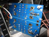
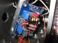
I went through the PCB and checked the joints along with the transistor
placement. Everything looked ok. I turned on...one meter went to 1250 and then went down slowly to zero...the other meter was zero. I then checked the voltage at the amp pcb. V + to V- was only 42 volts and V+ was 16 volts and V- was 5 or 6 volts. I now think something is not right in the power supply. I will take photo, or both PCB,s
placement. Everything looked ok. I turned on...one meter went to 1250 and then went down slowly to zero...the other meter was zero. I then checked the voltage at the amp pcb. V + to V- was only 42 volts and V+ was 16 volts and V- was 5 or 6 volts. I now think something is not right in the power supply. I will take photo, or both PCB,s

Thats a good idea...I had the parts before I had the boards...I ordered the PCB from the DIY Store but then there was a problem with the power board so I switched to this PCB.
Is an active preamp required with the F5 or is anyone using it with a plain old pot?
Thanks!
Kofi
Thanks!
Kofi
- Home
- Amplifiers
- Pass Labs
- An illustrated guide to building an F5