Interesting idea Salar, we have cheap tiny smd video amplifiers that were not available when CD was invented.
This is in 6 lead SOT-23, so still diyable. There are even smaller BGA, but hard to use.
https://www.analog.com/en/products/ada4807-1.html
Low noise and 200MHz GBW
https://www.analog.com/en/products/ada4807-1.html
Low noise and 200MHz GBW
Thanks David! But according to the datasheet, the proposed amplifier circuit
(Fig. 70) seems rather complicated.
I only need to double the current from the photodiodes
as the emitting laser diode early reaches lower threshold
and therefor changes beam characteristics...
I have many old players: Found this "Head Amp" TA7331P in a second generation Toshiba XR-Z70.
I own five, one is not working.
The XR-Z70 was rebadged for many other brands:
Alpine, NAD, Kenwood, Luxman, Uher.
But I have no clue about the amplification ratio...
Attachments
Last edited:
EDIT: There is an error in the datasheet: Q103 "TP7331P" is actually a TP7731P.
It is not amplifying the current, as far as I can see.
I cannot find a datsheet on this.
It is not amplifying the current, as far as I can see.
I cannot find a datsheet on this.
O.k., found a description in a Kenwood DP-1100B.
Two outputs have a feedback resistor for adjustable gain.
The B and C inputs coming from the photodiodes have to be reversed.
Still, as a layman I do not know: The TA7731P does an I/V conversion
and outputs a voltage, correct?
But the CX20109 input is fed by a current. So will I get an amplification in current?
Next week I will try the mod proposed earlier by changing the feedback resistors around CX20109. If this does not work, I will try a mod using the headamp TA7731P put before the CX20109.
All the best,
Salar
Attachments
The CX20109 inputs look to be configured as classic I/V convertors. The TA7731 will be similar and run with a fixed conversion ratio. The final output from both these chip is a voltage.
I know, but will the CX20109 input - designed for a current source -accept the output voltage of the TA7731?
Simple answer is no, not directly. The I/V is really like an opamp configured as an inverting stage and with the current (from the photo diode) fed directly into the inverting input.
You could add a series resistor to make it a conventional inverting voltage stage but then you are into deteriorating the signal with noise... whether that would matter I don't know.
You could add a series resistor to make it a conventional inverting voltage stage but then you are into deteriorating the signal with noise... whether that would matter I don't know.
Its not that simple...
If the photo diode delivers say 100uA and that is converted to 1 volt you can not then apply that voltage directly to another current input stage. You would need to convert that voltage to a current again which can be done by adding a series resistor in front of the next I/V stage. A 5k resistor would allow 200uA to flow into the next input stage (1V/5000) making that stage think it was seeing a 200uA photodiode current.
The big problems are noise (you are impairing the SNR) and also the real issue of DC level changes. The original circuit will not just need the wanted voltages/current, they also have to sit at the right static DC level.
Hello Mooly,
now I understand, thanks a lot indeed!
Now playing with the Feedback resistor values of R104/R105/R108/R109 I see thath they are
paralleld with capacitors. I find conflicting Info on that. Are they for avoiding DC-Offset or acting as low pass filters?
All the best,
Salar
now I understand, thanks a lot indeed!
Now playing with the Feedback resistor values of R104/R105/R108/R109 I see thath they are
paralleld with capacitors. I find conflicting Info on that. Are they for avoiding DC-Offset or acting as low pass filters?
All the best,
Salar
Last edited:
Hm - look like I just have to increase the value of the capacitors by the same ratio as the resisors...
It works.
At least for the feedback resistor of the internal RF-Amp
of CX20109. The resistor is between the pins 3&4.
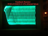
Below the eyepatterns of an aged laser diode (LT022MC) in a
Sony BU-1C. Right before the mod, left after the mod.
Before the modification the amplitude of the eyepattern it was about 0.7V p-p
almost half of the the original value, due to aging.
The feedback resistor was 18k.
I increased the feedback resistor to 27k.
Back to Ballpark - 1.2V!
Probably the first photo ever published of an amplified eyepattern,
that was raised in level by not touching the APC circuit 😀
So, this modification might help anyone who wants to extend the life
of a laser diodes life in a classical Sony CD-player using the CX20109 RF-Amp:
By lowering the current of the diode and raising the amplification of the CX20109.
The feedback resistors for the E-F opamps (RF104 / RF105) and focus error amp (R108 / R109) will be changed next.
Please note that the values of R108 / R 109 in post #18 I marked red are wrong.
They must be higher, not lower.
At least for the feedback resistor of the internal RF-Amp
of CX20109. The resistor is between the pins 3&4.
Below the eyepatterns of an aged laser diode (LT022MC) in a
Sony BU-1C. Right before the mod, left after the mod.
Before the modification the amplitude of the eyepattern it was about 0.7V p-p
almost half of the the original value, due to aging.
The feedback resistor was 18k.
I increased the feedback resistor to 27k.
Back to Ballpark - 1.2V!
Probably the first photo ever published of an amplified eyepattern,
that was raised in level by not touching the APC circuit 😀
So, this modification might help anyone who wants to extend the life
of a laser diodes life in a classical Sony CD-player using the CX20109 RF-Amp:
By lowering the current of the diode and raising the amplification of the CX20109.
The feedback resistors for the E-F opamps (RF104 / RF105) and focus error amp (R108 / R109) will be changed next.
Please note that the values of R108 / R 109 in post #18 I marked red are wrong.
They must be higher, not lower.
Attachments

Last edited:
An excellent and interesting result 🙂 It certainly opens a whole new can of worms for those who do have low output and obsolete pickups.
Good work
Good work
Thanks. But I have to figure the cutoff frequencies and by this the values of
the paralelled resisitors. I don not know if raising the value of the capacitors
by the same amount as the resistors -i.e one third for R104: From 390k/18pF to 560k/27pF - is the right math.
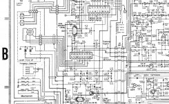
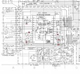
Here is the corrected schematic. Only R102 has been changed and tested for now.
the paralelled resisitors. I don not know if raising the value of the capacitors
by the same amount as the resistors -i.e one third for R104: From 390k/18pF to 560k/27pF - is the right math.
Here is the corrected schematic. Only R102 has been changed and tested for now.
Attachments
Hi Salar,
If you increase the amplifier gain, will laser power automatically drop since the following components: laser diode - monitor diode - RF amplifier are in a feedback loop? In other words, does your method work with healthy lasers, too?
If you increase the amplifier gain, will laser power automatically drop since the following components: laser diode - monitor diode - RF amplifier are in a feedback loop? In other words, does your method work with healthy lasers, too?
I suspect those caps are just for stability rather than to give some pre determined response. Normally you would decrease a cap value as the feedback resistor was raised.
The E and F diodes feed directly into the chip as expected and so tbh I'm not certain what those resistors actually do. They seem far to high in value to be feedback resistors around an I/V stage and so I wonder if they are just to supply some static low level bias of some kind. Not sure on that. You may well have enough extra gain available with the tracking and focus gain presets.
The E and F diodes feed directly into the chip as expected and so tbh I'm not certain what those resistors actually do. They seem far to high in value to be feedback resistors around an I/V stage and so I wonder if they are just to supply some static low level bias of some kind. Not sure on that. You may well have enough extra gain available with the tracking and focus gain presets.
The RF amp isn't in the feedback loop for the laser. The laser current is determined solely by an onboard photodiode mounted on the same die as the laser. Its a self contained circuit and nothing in the player has any input over it apart from its supply voltage and laser on/off command.
- Home
- Source & Line
- Digital Source
- An Idea for saving Laser Life - amplifying the current?