Hi there,
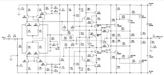
I came across Mr. Randy Slone's book about high power audio amplifiers and decided to build one my self. I chose the L-Mosfet design that has a 120W capability. I then built it, powered it up and what happened was that the connected speaker started making loude noise as soon as i powered it up, without any inputs whatsoever. I've been reading some threads on this forum which said that one design in his book is not working, but didnt quite catch which one is it. Hopefully not the one I chose. Anyways, if mine is supposed to work it would be helpful to recieve some oppinions on how to deal with my problem.
You should also know that I am a beginner when it comes to audio amplifier design, and in rush to finish this project.
I thank you for all your answers in advance.
Attachments
It is indeed a very complicated amplifier, I chose it for my final asignement in school, the thing is I'm not really sure if the design is working correctly. Has anyone succeeded to get it to work properly?
I definitly choose the correct transistors for the output all the components are correct I checked everything that could be checked and it seems to be okay.
It's too late now for me to change to another one, so I would rather try to solve the problem with this one.
I definitly choose the correct transistors for the output all the components are correct I checked everything that could be checked and it seems to be okay.
It's too late now for me to change to another one, so I would rather try to solve the problem with this one.
Not a good idea to fire a new amp connected to a speaker.
If you want to recycle your latfets, I recommend:
AEM6000 Based 100W Amp
AEM6000 Based 50W Amp
The latter is now my main amp.
If you want to recycle your latfets, I recommend:
AEM6000 Based 100W Amp
AEM6000 Based 50W Amp
The latter is now my main amp.
Well the schematics speaks for itself, I have a unregulated PSU +/-60V. I dont know what more could you need. The thing here is that I've read about this design being faulty. Something about the current for the VAS not being defined which burns the darlington transistors.
We do not even know it is stereo or not.
Did you use a circuit board and where does it come from.
Are you sure about supply and wiring which is not part
of the schematic shown.
Also your source of "design being faulty" is not known.
We are expected to work, but you are lazy.
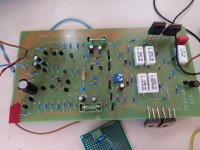
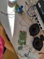
Alright first it is a mono amplifier, I am using a PCB that was produced by jlcpcb in china for both PSU and the amplifier. The supply wiring is hopefully correct I'm attaching a photo of the actual wiring there is +/-60V and ground returns to the PSU board connected all together.
Probabbly looks amateur to you but thats best I can do. Dont judge me.
Probabbly looks amateur to you but thats best I can do. Dont judge me.
Attachments
That Randy Slone design has a known fault where the VAS current is 'indeterminate'. It is the result of the LTP current mirrors feeding a symmetrical beta-enhanced VAS. Bob Cordell outlines this issue in his book and offers a solution. With some compromise you could ditch the mirrors and use resistive LTP loads as a quick fix, values determined by tail current and desired VAS current.
Undefined VAS current
Yes. This is a problem with symmetric IPS. The usual way to make a symmetrical IPS is to uses emitter resistors in the VAS and resistors instead of current mirrors on the LTP. Choose the LTP collector resistor for about one extra diode drop (Darlington VAS+1=3) given the LTP current (120*2 *3 = 720) and the VAS emitter resistor for a rational VAS current with the one extra diode drop ( 0.65/10mA ~= 68 Ohm). Simulating the circuit in SPICE is not really optional. Bare in mind that simulations are poor at predicting sensitivity to part variations unless you go to a lot of work stepping though transistor variations.
Having said that, the odds of building something this complicated without making a mistake are about zero. You have to build it a bit at a time, testing each bit as you go. You never begin by applying full power, ie without current limiting and never into a speaker.
Well the schematics speaks for itself, I have a unregulated PSU +/-60V. I dont know what more could you need. The thing here is that I've read about this design being faulty. Something about the current for the VAS not being defined which burns the darlington transistors.
Yes. This is a problem with symmetric IPS. The usual way to make a symmetrical IPS is to uses emitter resistors in the VAS and resistors instead of current mirrors on the LTP. Choose the LTP collector resistor for about one extra diode drop (Darlington VAS+1=3) given the LTP current (120*2 *3 = 720) and the VAS emitter resistor for a rational VAS current with the one extra diode drop ( 0.65/10mA ~= 68 Ohm). Simulating the circuit in SPICE is not really optional. Bare in mind that simulations are poor at predicting sensitivity to part variations unless you go to a lot of work stepping though transistor variations.
Having said that, the odds of building something this complicated without making a mistake are about zero. You have to build it a bit at a time, testing each bit as you go. You never begin by applying full power, ie without current limiting and never into a speaker.
Hi there,
I came across Mr. Randy Slone's book about high power audio amplifiers and decided to build one my self. I chose the L-Mosfet design that has a 120W capability. I then built it, powered it up and what happened was that the connected speaker started making loude noise as soon as i powered it up, without any inputs whatsoever. I've been reading some threads on this forum which said that one design in his book is not working, but didnt quite catch which one is it. Hopefully not the one I chose. Anyways, if mine is supposed to work it would be helpful to recieve some oppinions on how to deal with my problem.
You should also know that I am a beginner when it comes to audio amplifier design, and in rush to finish this project.
I thank you for all your answers in advance.
What needs attention is how the amp is supposed to settle an operating point. Both input LTP's have a CCS at "bottom" but also 1 "in top". Without an extra loop to balance "bottom" and "top" current sources, the amp is unlikely to work. Hence replace "top" current sources with resistor to set current through Q11 & 12 and then, if THD / IMD is above design goal, make some adjustments.
How sure are you that the PCB is exactly like the circuit? It doesn't look like it was laid out with the help of a netlist.
So chances that it has zero errors are just that.
You said you ran out of time to switch to another (simpler) design, but what are the consequences if you never get this to work?
"Out of time" is a relative thing.
Jan
So chances that it has zero errors are just that.
You said you ran out of time to switch to another (simpler) design, but what are the consequences if you never get this to work?
"Out of time" is a relative thing.
Jan
Where did you get that PCB from did you make it yourself? It looks like a single channel board so why are the two power transistors at the bottom not connected. You should also put all power transistors on a heatsink. It probably wont set up properly without one. Can you also show us the bottom of the board as well please?
- Status
- This old topic is closed. If you want to reopen this topic, contact a moderator using the "Report Post" button.
- Home
- Amplifiers
- Solid State
- An audio amplifier I built doesn' work