Yes, exactly: the discussion has drifted into nitpicking about a very accessory and minor point, but that is the way forums operate....Interesting discussion on sampling, data set size and statistical outcome... but isn't the point to make the C-Vac a perfect mimic of whichever real tube that we plug into it? So if we sort through our collection of 12AT7 and find the most linear one in the bunch, we will then end up with the most linear output except multiplied 555 times - regardless of what the datasheet or the SPICE model says. Right?
Jaz
I really don't think that using 555 12AT7's is a good idea. You should consider that 555 of these will consume more than 1KW for filament supply!!
Solid state people always forget vacuum tubes do have filaments.... 😀
Solid state people always forget vacuum tubes do have filaments.... 😀
Exactly, that is the point of these threadsI really don't think that using 555 12AT7's is a good idea.
We could add that apparently, vacuum people forget to read more than the few last messages in the thread before answering....Solid state people always forget vacuum tubes do have filaments.... 😀
Exactly, that is the point of these threads
We could add that apparently, vacuum people forget to read more than the few last messages in the thread before answering....
I think your first message was: "Ever wondered how a push pull composed of 555 paralleled 12AT7 would sound?"
Before uleashing your fantasy you should at least check this is common sense or not. That was my point.
However even assuming that you want to waste 1.5-2KW (filament + plate consumption) per channel (!!?!) the answer is rather simple: 99.9999999% it cannot compete with 1 or few proper devices doing the same job regardless of theories and modelling because at end you must deal with REAL devices! Don't tell me that you want to buy thousands of 12AT7's to select 555.....it's just madness for me. Paralleling more than 4-5 devices is usually already challenging.
I know that someone has made amps using lots of signal devices in parellel but that doesn't mean anything. I just see it as a techincal exercise......
Last edited:
Yeah Elvee, how bout them filaments??? Series or Parallel??? Juskiddin..
Each triode (to be copied 554 times in sand) needs only one filament.
The missing glow and heat compensated by a large lump of Radium.
But if the point is to be true to a push pull OTL amplifier of 1110 real
output triodes? Then you need to simulate triodes that don't match,
and all the Miller capacitance... I think that would be pointless, as
those are flaws better avoided anyway. I'm all for the copy, just so
we know its not entirely realistic for good reasons.
Last edited:
I hesitated to post here because this thread looked like it was turning into an argument contest. Regardless of the nit-picking I have been tinkering with current mirror fed amps off and on for a few years. They do work, and can be made to sound good. Mine are still sand assisted glass based though.
I find that the best sounding setup so far is an SE amp that uses a 45 as the master, and a triode wired sweep tube (currently a 6LW6) as the slave. There is a 10:1 current mirror in the cathodes, both plates are tied together feeding a 600 ohm OPT. The grid of the 45 is driven and at DC zero volts. The grid of the 6LW6 is a few volts negative and at AC ground.
I haven't tinkered with this in a while but I came to the realization that I was limited by the quality of the cheap Chinese OPT. I tried just using the current mirror output, and using regulator triodes (6AS7G and 6336A) for the output, but it worked best when the slave output device was a triode with Mu about the same as the 45 (master).
Let's say it is a rhetorical question. However, if you toy with the idea of paralleling a number of tubes, C-Vac is is a useful tool to test the idea almost for real, without the problems and expenses associated with real glass.I think your first message was: "Ever wondered how a push pull composed of 555 paralleled 12AT7 would sound?"
Yeah, the OPT is often a limiting factor, and it was one of the main drivers behind C-Vac.I find that the best sounding setup so far is an SE amp that uses a 45 as the master, and a triode wired sweep tube (currently a 6LW6) as the slave. There is a 10:1 current mirror in the cathodes, both plates are tied together feeding a 600 ohm OPT. The grid of the 45 is driven and at DC zero volts. The grid of the 6LW6 is a few volts negative and at AC ground.
I haven't tinkered with this in a while but I came to the realization that I was limited by the quality of the cheap Chinese OPT.
It can of course be used as a regular current mirror: see below for a P example.
The main superiority compared to a regular current mirror is the ability to operate in a fully floating manner.
That sounds logical.I tried just using the current mirror output, and using regulator triodes (6AS7G and 6336A) for the output, but it worked best when the slave output device was a triode with Mu about the same as the 45 (master).
Attachments
Last edited:
Miller might be there somewhere, but V2 isn't going to feel it.
Driving it is not like driving 555 real triodes was my point...
Not that you would want to...
----
Anyways, in the spirit of friendly nitpicking, I'm working on
that compelling example thing you asked for. Here's what I
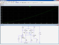
got so far (This is the dumb model, pure Child-Langmuir):
.SUBCKT AT7 PLATE GRID CATHODE
.param MU=60
.param PERVEANCE=.0221
G1 PLATE CATHODE VALUE=
+{PWR(PERVEANCE*(V(GRID,CATHODE)+(V(PLATE,CATHODE)/MU)),1.5)}
R1 PLATE CATHODE 999G ; prevent floating nodes
R2 GRID CATHODE 999G ; pervent floating nodes
.ENDS
Then later (maybe lots later) I will attempt to fake the real curves by
parallel internal paths, rather than Koren's more efficient methods of
fudging the equation for lean...
Note to future self:
I need to limit this .model to keep it from going silly beyond cutoff.
Driving it is not like driving 555 real triodes was my point...
Not that you would want to...
----
Anyways, in the spirit of friendly nitpicking, I'm working on
that compelling example thing you asked for. Here's what I
got so far (This is the dumb model, pure Child-Langmuir):
.SUBCKT AT7 PLATE GRID CATHODE
.param MU=60
.param PERVEANCE=.0221
G1 PLATE CATHODE VALUE=
+{PWR(PERVEANCE*(V(GRID,CATHODE)+(V(PLATE,CATHODE)/MU)),1.5)}
R1 PLATE CATHODE 999G ; prevent floating nodes
R2 GRID CATHODE 999G ; pervent floating nodes
.ENDS
Then later (maybe lots later) I will attempt to fake the real curves by
parallel internal paths, rather than Koren's more efficient methods of
fudging the equation for lean...
Note to future self:
I need to limit this .model to keep it from going silly beyond cutoff.
Last edited:
RE: 45
There is only one or two tubes in this scheme, not 555 or 1110!
RE: Elvee
P-chan C-Vac
I assume the actual output there would be from the "ground" terminal, with a fixed total B+ for a set of N-Chan and P-chan C-Vac's stacked up for a P-P output case. (So that the tube(s) see the variation of output voltage on it's plate(s), to maintain triode-like behavior.)
Something to still consider would be if it is practical to make the control input to a C-Vac emulation P-chan like also.
A differential pair (CCS tail) of tubes at the "pilot" position, or a differential pair using a Fet and a tube maybe. Tube on one side of the differential gives a P-chan input emulation of the tube, and swap the two in the differential pair to get an "anti-triode" tube emulation. "Pilot" tube (or the "anti-tube") gets its plate current monitored, like in the P-C-Vac. Kenpeter will have more to say on the concept I think.
Last edited:
I think the more you keep with the simple ^3/2, the more it will prove your point (sort of): averaging of non-linear functions using simple arithmetic average is certainly not a valid method, generally speaking to obtain an average similar function:Then later (maybe lots later) I will attempt to fake the real curves by
parallel internal paths, rather than Koren's more efficient methods of
fudging the equation for lean...
One could think of functions having a marked hump at a certain Vgk: it is obvious that averaging many such functions having the hump at different places will yield a result having no hump at all, and therefore non-characteristic.
But here we are dealing with a very modest exponent (>=3 would be required to create a hump), and modest deviations from sample to sample.
In addition, the reality as you want to model it will dilute further the already shallow function: what you propose is to simulate each tube with a number of fragmented and slightly different sub-tubes. Merging them in a super-tube will simply increase the dilution and fuzziness factor, IMHO
I am aware that that is not what you are looking for: I am thinking about it, and so far I can find no satisfactory solution.RE: Elvee
P-chan C-Vac
I assume the actual output there would be from the "ground" terminal, with a fixed total B+ for a set of N-Chan and P-chan C-Vac's stacked up for a P-P output case. (So that the tube(s) see the variation of output voltage on it's plate(s), to maintain triode-like behavior.)
Something to still consider would be if it is practical to make the control input to a C-Vac emulation P-chan like also.
A differential pair (CCS tail) of tubes at the "pilot" position, or a differential pair using a Fet and a tube maybe. Tube on one side of the differential gives a P-chan input emulation of the tube, and swap the two in the differential pair to get an "anti-triode" tube emulation. "Pilot" tube (or the "anti-tube") gets its plate current monitored, like in the P-C-Vac. Kenpeter will have more to say on the concept I think.
It would involve a floating current sensing, decoupled from the output.
I will continue to think about it, and maybe I (or somebody else)will find a simple, effective and elegant solution, in a month, a year, or never, who knows... Be assured that it stays in the corner of my mind though: when I have a sleepless night, I will think about it (that is the best moment to find the solution to that kind of problem, for me at least)
Yeah, the OPT is often a limiting factor, and it was one of the main drivers behind C-Vac.
I knew this was the main reason and I welcome your solution for cheaper alternatives but it is better to talk about it for what it is....
The output transformer is a limiting factor ONLY when you cannot afford a good one!😀
This has also generated the false myth that OTL amps in principle are better. No way, I am afraid! 😀
The best power stage is: vacuum tubes + output transformer. Sound-wise is still unbeaten. 🙂
I prefer solid state a low signal level for phono preamp mostly. At line level the two technologies are more or less equivalent, each one with its pros and cons.
Last edited:
This for me, was not the quickest nor easiest way to model a triode.
But it does prove my insane method and lame reasoning behind it.
You only need parallel Child Langmuir to explain lean, nothing else.
If we extend the parameter spread across hundreds of unmatched
triodes, the lean could only increase. How much? I don't know. If I
knew (which I don't), I'd hazard a guess that a carefully selected
spread of just two already leaning triodes could probably fake it.
Not that further spreading the parameters is desirable, only that
is required if you wish to sound like the parameter smear of 555
unmatched triodes, which we probably don't.
---
So, anyways. This is a simulation of a theoretically pure AT7 curve
set of one Child-Langmuir law, then a spread of 10 subset-triodes
that have been empirically chosen to lean like the spec sheet.
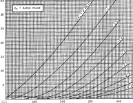
Enjoy, and "reload plot settings" if you want the scale to look like
the spec sheet, for easy side by side comparison...
But it does prove my insane method and lame reasoning behind it.
You only need parallel Child Langmuir to explain lean, nothing else.
If we extend the parameter spread across hundreds of unmatched
triodes, the lean could only increase. How much? I don't know. If I
knew (which I don't), I'd hazard a guess that a carefully selected
spread of just two already leaning triodes could probably fake it.
Not that further spreading the parameters is desirable, only that
is required if you wish to sound like the parameter smear of 555
unmatched triodes, which we probably don't.
---
So, anyways. This is a simulation of a theoretically pure AT7 curve
set of one Child-Langmuir law, then a spread of 10 subset-triodes
that have been empirically chosen to lean like the spec sheet.
Enjoy, and "reload plot settings" if you want the scale to look like
the spec sheet, for easy side by side comparison...
Attachments
.SUBCKT AT7 PLATE GRID CATHODE
.param MU0=35 PV0=.00015
.param MU1=40 PV1=.00016
.param MU2=45 PV2=.00018
.param MU3=50 PV3=.00020
.param MU4=55 PV4=.00025
.param MU5=60 PV5=.00030
.param MU6=65 PV6=.00035
.param MU7=70 PV7=.00040
.param MU8=75 PV8=.00045
.param MU9=80 PV9=.00050
G1 PLATE CATHODE VALUE={
+MAX(0,PV0*PWRS(V(GRID,CATHODE)+(V(PLATE,CATHODE)/MU0),1.5))+
+MAX(0,PV1*PWRS(V(GRID,CATHODE)+(V(PLATE,CATHODE)/MU1),1.5))+
+MAX(0,PV2*PWRS(V(GRID,CATHODE)+(V(PLATE,CATHODE)/MU2),1.5))+
+MAX(0,PV3*PWRS(V(GRID,CATHODE)+(V(PLATE,CATHODE)/MU3),1.5))+
+MAX(0,PV4*PWRS(V(GRID,CATHODE)+(V(PLATE,CATHODE)/MU4),1.5))+
+MAX(0,PV5*PWRS(V(GRID,CATHODE)+(V(PLATE,CATHODE)/MU5),1.5))+
+MAX(0,PV6*PWRS(V(GRID,CATHODE)+(V(PLATE,CATHODE)/MU6),1.5))+
+MAX(0,PV7*PWRS(V(GRID,CATHODE)+(V(PLATE,CATHODE)/MU7),1.5))+
+MAX(0,PV8*PWRS(V(GRID,CATHODE)+(V(PLATE,CATHODE)/MU8),1.5))+
+MAX(0,PV9*PWRS(V(GRID,CATHODE)+(V(PLATE,CATHODE)/MU9),1.5))}
R1 PLATE CATHODE 999G ; prevent floating nodes
R2 GRID CATHODE 999G ; pervent floating nodes
.ENDS
Attachments
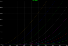
At the bottom, where lines crunch to the left, I see Mu=35.
Perfect sense, since lowest Mu path should be last to cut off.
I hope Smoking-amp is happy to see his old theory proven.
Perfect sense, since lowest Mu path should be last to cut off.
I hope Smoking-amp is happy to see his old theory proven.
Last edited:
In principle, yes they are better: for one they don't have the distortion of the iron, which exists in all transformers including the very best, and more importantly the transformer limits the amount of feedback that can be applied to the amplifier to correct this type of distortion and othersThis has also generated the false myth that OTL amps in principle are better. No way, I am afraid! 😀
Exactly: that is just a matter of taste, and that may also explain why germanium amplifiers are preferred by some, because they are also colored by the iron.The best power stage is: vacuum tubes + output transformer. Sound-wise is still unbeaten. 🙂
Here you areElvee can you post the .asc file so we can optimize it quickly?
Thank you!
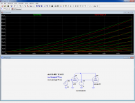
The modelling used by Duncan for example is quite different (and more complex), and it gives more realistic results.This for me, was not the quickest nor easiest way to model a triode.
But it does prove my insane method and lame reasoning behind it.
You only need parallel Child Langmuir to explain lean, nothing else.
Here the sets of curves are adjusted for the best fit, but severe discrepancies remain.
Attachments
In principle, yes they are better: for one they don't have the distortion of the iron, which exists in all transformers including the very best, and more importantly the transformer limits the amount of feedback that can be applied to the amplifier to correct this type of distortion and others
I disagree. Still have to listen to an OTL that's good enough....
There are a good number of really good transformers (at affordable prices) that allow to use easily 12-15 FB without any compensation. In best cases you can go up to 20-25 dB if you wish without any stability issue. I don't think you need more than this. If you need it I would rather think that the design is not so good....
Moreover you can use cathode feedback with indipendent tertiray winding, plate to grid feedback and other kinds of local nested FB. Your thinking seems to be stuck onto one topology adopted by most manufacturers to save costs, not really quality items.
It's not true that the OTL distortion is lower, if the transformer is good its distortion is much lower that that generated by the active stages and you have no insulation. Moreover if you don't use the secondary for loop feedback this can be floating and therefore there is no loop of any kind that can run into the speakers.....the transformer is simply the best device to link sources to amps and amps to speakers.
The low distortion applies to low level transformer as well. You can easily have line level (or lower) transformers that produce -110 to -120 dB THD at their working level and more!
Last edited:
Typical answer of "the fox that cannot reach the grapes"....Exactly: that is just a matter of taste, and that may also explain why germanium amplifiers are preferred by some, because they are also colored by the iron.
Yes sure, your (odd) amp is better.
Bye
Oh yeah, there are so many more things to adjust for an accurate model.severe discrepancies remain.
And best fit behavioral equations like Duncan's are totally the way to go.
I didn't bother with grid current, or Miller, and whatever makes the 0
line bump up I couldn't even begin to guess the math of those things...
Koren said, "New equations for tube characteristics are phenomenological
equations, that is, equations model the behavior of physical phenomena
using a reasonable number of parameters, but are not derived from
fundamental physics."
I was only concerned to demonstrate convincingly the leaning behavior
of parallel triodes is likely a feature aggravated by unmatched set size.
And I believe what I'm showing about sets might be the actual physics.
I acknowledge the discrepancy you point out as real, no argument...
Last edited:
That is mixing up of emotional and technical issues.I disagree. Still have to listen to an OTL that's good enough....
There are a good number of really good transformers (at affordable prices) that allow to use easily 12-15 FB without any compensation. In best cases you can go up to 20-25 dB if you wish without any stability issue. I don't think you need more than this. If you need it I would rather think that the design is not so good....
Moreover you can use cathode feedback with indipendent tertiray winding, plate to grid feedback and other kinds of local nested FB. Your thinking seems to be stuck onto one topology adopted by most manufacturers to save costs, not really quality items.
It's not true that the OTL distortion is lower, if the transformer is good its distortion is much lower that that generated by the active stages
On the principle, when you have situation a/One active element (more or less linear) and the maximum possible feedback available, compared to situation b/The same active element, a distortion generating block (as little or as much as you want), and a limited amount of FB available, it is clear that a/ will always be better than b/.
There would be one exception: if the non-linearities of the active element compensate exactly those of the additional block (transformer), but that is more than unlikely to happen at random.
Transformers are great intellectual shortcuts for designers: they can translate to any voltage, adapt impedances, with no headaches, and apparently at no cost. Really? Are there free lunches in enginreering?and you have no insulation. Moreover if you don't use the secondary for loop feedback this can be floating and therefore there is no loop of any kind that can run into the speakers.....the transformer is simply the best device to link sources to amps and amps to speakers.
The low distortion applies to low level transformer as well. You can easily have line level (or lower) transformers that produce -110 to -120 dB THD at their working level and more!
Anyway, it is visibly useless to continue arguing, you are visibly a fan of the transformers, output, input, drivers, interstage..... and you hate OTL's. Why not, we are all free, but in those conditions, why participate to this thread? You are like a militant carnivorous trying to explain to a congress of vegetarians that meat is better.
Wondering who is the fox in this story, anyway I have never claimed that my "odd" amp is better, quite the contrary:Typical answer of "the fox that cannot reach the grapes"....
Yes sure, your (odd) amp is better.
You could find the answer here: SolidGlass is an experimental OTL amplifier using and displaying the C-Vac concept (more details here).
...
It is a rather simplistic amplifier, no rocket science involved, just a showcase/proof of concept for OTL amplifiers based on C-Vac.
It uses only four triodes, and has a low feedback factor. This means that it remains true to its glass nature, with the colorations typical of tubes almost unattenuated.
.....
Note that I don't recommend investing lots of time, money and attention in this amplifier: it has little merit or originality, its main purpose is to test and present the C-Vac principles, and it has not been researched and optimized the way other projects have been.
The important things here are the respective importances of internal variation (micro-tubes inside one tube) vs the external variation from tube to tube.Oh yeah, there are so many more things to adjust for an accurate model.
And best fit behavioral equations like Duncan's are totally the way to go.
I didn't bother with grid current, or Miller, and whatever makes the 0
line bump up I couldn't even begin to guess the math of those things...
Koren said, "New equations for tube characteristics are phenomenological
equations, that is, equations model the behavior of physical phenomena
using a reasonable number of parameters, but are not derived from
fundamental physics."
I was only concerned to demonstrate convincingly the leaning behavior
of parallel triodes is likely a feature aggravated by unmatched set size.
And I believe what I'm showing about sets might be the actual physics.
I acknowledge the discrepancy you point out as real, no argument...
From what I see, you had to resort to a ~3:1 parameter variation inside one tube. Would the parameter variation from tube to tube be on the same order? I don't think so, unless the tubes are different types, like I did in my quick and dirty example.
- Status
- Not open for further replies.
- Home
- Amplifiers
- Tubes / Valves
- An application of C-Vac: the SolidGlass amplifier