Ever wondered how a push pull composed of 555 paralleled 12AT7 would sound?
You could find the answer here: SolidGlass is an experimental OTL amplifier using and displaying the C-Vac concept (more details here). In short, C-Vac is an accurate “device multiplier”, capable of generating an enlarged copy of the model provided, low-power triodes in this case.
The concept lends itself to OTL amplifiers, and this is what SolidGlass is about.
It is a rather simplistic amplifier, no rocket science involved, just a showcase/proof of concept for OTL amplifiers based on C-Vac.
It uses only four triodes, and has a low feedback factor. This means that it remains true to its glass nature, with the colorations typical of tubes almost unattenuated.
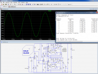
It operates in class AB, at a quiescent current of 200mA. The maximum output power is ~70W on a 16Ω load for 0.5V rms input voltage.
That power is attained at a THD level of less than 0.4%.
The distortion profile is very gentle, and typical of a good, low GNFB tube amplifier, which is exactly the purpose of this project.
The dissipated power is pretty high: about 40W under quiescent conditions and much more at a high output power, but this shouldn't frighten tube lovers.
Note that I don't recommend investing lots of time, money and attention in this amplifier: it has little merit or originality, its main purpose is to test and present the C-Vac principles, and it has not been researched and optimized the way other projects have been.
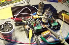
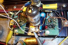
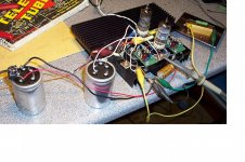
I recommend a quick and dirty point-to-point prototype, just like mine to get a taste of the thing. If you like it, it will always be possible to elaborate and refine.
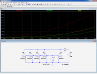
The two dotted boxes in the schematic are the two C-Vac units, each equivalent to 555 paralleled 12AT7, refer to the post in the Solid State section for more details.
The rest of the amp is relatively straightforward, and should need no additional explanations.
You could find the answer here: SolidGlass is an experimental OTL amplifier using and displaying the C-Vac concept (more details here). In short, C-Vac is an accurate “device multiplier”, capable of generating an enlarged copy of the model provided, low-power triodes in this case.
The concept lends itself to OTL amplifiers, and this is what SolidGlass is about.
It is a rather simplistic amplifier, no rocket science involved, just a showcase/proof of concept for OTL amplifiers based on C-Vac.
It uses only four triodes, and has a low feedback factor. This means that it remains true to its glass nature, with the colorations typical of tubes almost unattenuated.
It operates in class AB, at a quiescent current of 200mA. The maximum output power is ~70W on a 16Ω load for 0.5V rms input voltage.
That power is attained at a THD level of less than 0.4%.
The distortion profile is very gentle, and typical of a good, low GNFB tube amplifier, which is exactly the purpose of this project.
The dissipated power is pretty high: about 40W under quiescent conditions and much more at a high output power, but this shouldn't frighten tube lovers.
Note that I don't recommend investing lots of time, money and attention in this amplifier: it has little merit or originality, its main purpose is to test and present the C-Vac principles, and it has not been researched and optimized the way other projects have been.
I recommend a quick and dirty point-to-point prototype, just like mine to get a taste of the thing. If you like it, it will always be possible to elaborate and refine.
The two dotted boxes in the schematic are the two C-Vac units, each equivalent to 555 paralleled 12AT7, refer to the post in the Solid State section for more details.
The rest of the amp is relatively straightforward, and should need no additional explanations.
Attachments
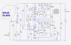
I see that I forgot a small detail on the schematic: in my prototype, I also have 33Ω+12V zeners as gate stoppers/protection. They don't change anything to the functioning of the amp, but it is safer to implement them.
Very interesting approach. The idea of SS current multipliers (C-Vac) for tubes have actually come up many times before. Broskie refers to them as impedance multipliers. The implimentation you have here is new however. I assume the inverted differentials ( Rush Cascode: Q6,Q7,Q8,Q9 ....) here are performing with less distortion than a conventional differential pair? (or is it just for neg. voltage limitation?) Do you have a plot of distortion for a C-Vac unit alone? Wouldn't a bit more voltage on the Q7,Q8 collectors help out a bit? (ie, bottom of R19 or R5 instead) The bootstrap load on U3, for the totem pole drive connected to the top of R19, instead of the bottom, looks good for removing the R20 sampling artifact. Plate voltage on the tube "pilots" is a replica of the output signal. Nicely done.
Some work needed yet to reduce the SS supply voltages for efficiency, yet preserve a faithful plate voltage on the "pilot" tubes. Some small 4:1 xfmrs for tube plate bootstraps could work.
A link to the C-Vac thread in the SS forum:
http://www.diyaudio.com/forums/solid-state/235115-new-hybrid-concept-c-vac.html
Last edited:
Developing a P channel device C-Vac could also help for separation of the tube and SS output power supplies. (for efficiency) Sample the current in the "pilot" plate instead.
Pentode "pilot"s could also be used to reduce voltage. The lower V screen grid gets used for the HV feedback, instead of the plate. Outputs still taken from the cathode or plate.
Pentode "pilot"s could also be used to reduce voltage. The lower V screen grid gets used for the HV feedback, instead of the plate. Outputs still taken from the cathode or plate.
Last edited:
Yes, I am aware there have been many tentatives into that direction, but I wanted to bring mainly two new features:Very interesting approach. The idea of SS current multipliers (C-Vac) for tubes have actually come up many times before. Broskie refers to them as impedance multipliers. The implimentation you have here is new however.
-A very accurate and deterministic multiplication process,
-A virtual component that is a perfect, indistinguishable copy a real tube, that can be plugged into any tube circuit and work exactly as its glass counterpart, without limitations, auxiliary pins or supplies, etc.
In fact, you could build the thing with a sube socket and use it as a plug-in replacement.
This topology was used mainly to avoid auxiliary supplies or bias, while performing practically as well as an LTPI assume the inverted differentials ( Rush Cascode: Q6,Q7,Q8,Q9 ....) here are performing with less distortion than a conventional differential pair? (or is it just for neg. voltage limitation?)
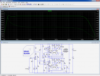
See below (at an A-K voltage of 150V).Do you have a plot of distortion for a C-Vac unit alone?
It would change very little. This configuration was used to make sure the bias currents were taken into account in the computation of the multiplied current for a maximum accuracy. Here, the bias currents are so low and the multiplication factor so high that in fact it matters very little, but this make the circuit more general: it could for instance be used to "help a bit" an already large tube, with a modest multiplication factor of 2 or 3.Wouldn't a bit more voltage on the Q7,Q8 collectors help out a bit?
I will think about it (and try to avoid transformers)Some work needed yet to reduce the SS supply voltages for efficiency, yet preserve a faithful plate voltage on the "pilot" tubes. Some small 4:1 xfmrs for tube plate bootstraps could work.
I will try to come up with an elegant solutionDeveloping a P channel device C-Vac could also help for separation of the tube and SS output power supplies. (for efficiency) Sample the current in the "pilot" plate instead.
It is of course a possibility (and a cheap alternative to wiring 555 12AT7's in parallel), but remember, C-Vac is mainly about making tube-OTL amplifiers easily possible.i was expecting to see an PPP 12at7 amplifer with 555 tubes.
I will probably make another test amplifier or two, like a direct-coupled SE amplifier
Attachments

555 real 12AT7's would not behave like one multipled 554 times.
In fact, the reason triode curves bend is because even with one
triode, you have multiple diffferent triode paths in parallel.
Summed curves "should" remain parallel, but set size isn't constant.
Those slopes that cut off earliest take themselves out of the process.
So, curves of the totaled set will have "lean to the right" appearance.
The more triodes, the more unmatched, the more lean.... 555 real
triodes will lean more than 554 simulated triodes of exact match.
You can simulate plausible triode lean by summing at least 4
well chosen fakes with slightly different perfect parallel curves.
You already have a leaning set of real curves, I'm just saying
its not the same curve as you would get with a larger set.
Last edited:
Well, the C-Vac simulation distortion looks pretty good. Probably will have to match the Rush cascode transistors for similar real circuit results. Maybe a fast Op Amp could provide the same function, if not power supply limited.
555 real 12AT7's would not behave like one multipled 554 times.
In fact, the reason triode curves bend is because even with one
triode, you have multiple diffferent triode paths in parallel.
Summed curves "should" remain parallel, but set size isn't constant.
Those slopes that cut off earliest take themselves out of the process.
So, curves of the totaled set will have "lean to the right" appearance.
The more triodes, the more unmatched, the more lean.... 555 real
triodes will lean more than 554 simulated triodes of exact match.
Interesting point, but it means that a real bunch composed of 555 actual valves will be disproportionately influenced by the most "aggressive" ones, and the result will be an atypical composite, bent towards one side of the distribution. It will however stay within the normal spread of these tubes.
With C-Vac, the result will be centered on the model, whatever it is.
If you pick and chose an "aggressive" tube as a model, you will reproduce this effect.
Not that I think it is really important: the average 12AT7 linearly multiplied by 555 may look more like a power triode, but in the end it will be a triode, perhaps a bit atypical considering the model but no more: tubes do have a serious spread to begin with, and when they age it increases further, so nothing shocking there.
Here, we have talked about triodes only, but other tubes like pentodes could be used as models. The secondary electrodes can be tied to their normal operating potentials, and if a grid current needs to be scaled, an opposite polarity C-Vac could do the job.
Two matched pairs can do the job, or even an array of complementary transistors: there must be a CA<something> or a MPQ<something else> doing that, but I am unable to remember the exact type numbers at the moment.Well, the C-Vac simulation distortion looks pretty good. Probably will have to match the Rush cascode transistors for similar real circuit results. Maybe a fast Op Amp could provide the same function, if not power supply limited.
Interesting point, but it means that a real bunch composed of 555 actual valves will be disproportionately influenced by the most "aggressive" ones, and the result will be an atypical composite, bent towards one side of the distribution. It will however stay within the normal spread of these tubes.
Nah, you got it backward. The most easily cut off paths take themselves
out of the set, causing lean. Strong paths that never cut off, but stay in
set always, are simply summed. Or averaged, if we only look at slopes.
There is nothing here to make the average look anything but average...
Its only when the set is reduced that lean occurs. Scrunched to the left at
the bottom (near cutoff), or spread at the top (away from cutoff), whatever
way you might wish to look at it...
Triodes with flat parallel construction almost always sport curves that are
nearly parallel. And those with internal construction of convenience with
no attempt to equalize all paths are usually the leaners.
Unless, by aggressive, you meant paths aggressively cutting off?
Then we might be on the same page...
Last edited:
We agree, but...Nah, you got it backward. The most easily cut off paths take themselves
out of the set, causing lean. Strong paths that never cut off, but stay in
set always, are simply summed. Or averaged, if we only look at slopes.
There is nothing here to make the average look anything but average...
You seem to contradict yourself:
Anyway, what I mean is that the total set will be bent towards the elements requiring the largest cut-off voltage.Unless, by aggressive, you meant paths aggressively cutting off?
Then we might be on the same page...
However, although atypical, this composite will stay within the limits of the datasheet
Total Gm doesn't somehow get bigger and better as weak paths drop out.
Neither does the average, if we consider the averaged set of curves (for
comparison with curves of a single triode) to have a constant divisor that
is fixed to the largest set size, and doesn't change with active set size.
There are often more weak (easily cut off) paths than strong ones, and they
are significant to the total Gm, especially noticeable when they go missing.
Probably not relevant to the written part of the datasheet, but the curves
of unmatched sets are definitely gonna be less parallel, the larger the set.
I sometime wonder if the lean as charaterized in a spec sheet is already
exaggerated in some manner due to the characterization of a larger set?
Any individual triode might perform with better "parallelity". I just made
up that word. We may never know what statistical method was used to
conclude the "typical" curve set. To me, those curves are just an artist's
concept.
Last edited:
I don't see how that's mathematically possible.Total Gm doesn't somehow get bigger and better as weak paths drop out.
Neither does the average, if we consider the averaged set of curves (for
comparison with curves of a single triode) to have a constant divisor that
is fixed to the largest set size, and doesn't change with active set size.
Here is what I mean:
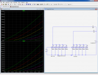
5 tubes are paralleled. For the sake argument, let's say they are all the same type, with the 12AT7 representing the "strong" extreme permitted by the datasheet, and the 12AX7 the "weak" one (OK, a bit far-fetched, but with a monte-carlo of the parameters, the result would be similar).
The area between the green and the red curves is the allowed spread for tubes of this type.
Here, we have one strong tube and four weak ones, the yellow curve being the arithmetic average of the complete set: it lies closer to the green curve, but well within the allowed space. No combination of weak or strong tubes could fall outside these limits, no matter how large is the set.
Attachments
I=Perveance*(Vgrid+(Vplate/Mu))^(3/2)
There's a lot of adjustments to Koren's law that better fudge a real triode.
But you don't really need other math. Just compute four or more slightly
different triodes with "perfect" parallel curves, and sum them... Boom!
There you got realistic leaning non-parallel curves, go figure....
---
Need to divide by Gm if you gonna compare the shape of apples to oranges.
5*12AT7 is obviously > 5*12AX7. Average falling between those extreme
lines can be no other way. There is a point to this if you do the right math.
Last edited:
Imagine your three curves scaled to all meet at the upper right...
One of them cuts off much more gradually than the other two.
Surprise! Its the average curve that does this.... Now ask why.
One of them cuts off much more gradually than the other two.
Surprise! Its the average curve that does this.... Now ask why.
That is basically my point, and since variations for a single tube type will obviously be smaller than with two different ones, the delta's will remain small.Average falling between those extreme
lines can be no other way. There is a point to this if you do the right math.
To repeat: the resulting composite tube wil be atypical, but within the spread allowed by the datasheet if each member respects that condition
You are not allowed to bend things in this way: this supposes you can have access to all the parameters of the tube separately, at will.Imagine your three curves scaled to all meet at the upper right...
One of them cuts off much more gradually than the other two.
Surprise! Its the average curve that does this.... Now ask why.
If you look at the families of curves for homogeneous and heterogeneous bunches, there is no significant difference in the general outlook (except the absolute numerical values), and the parallelism is approximate on both sides, no worst or better.
Attachments
Thats pretty convincing pair of graphs to say it makes no difference.
But I notice severe lean in the homogeneous model to begin with.
If real at7 has this much lean, then it might not make a difference.
I'm sure somewhere in this forum we can dig up a real 12AT7 trace
or two, to see if the model was based on reality. Or book picture of
"typical" that maybe already represents exaggerated lean of a set.
Interesting discussion on sampling, data set size and statistical outcome... but isn't the point to make the C-Vac a perfect mimic of whichever real tube that we plug into it? So if we sort through our collection of 12AT7 and find the most linear one in the bunch, we will then end up with the most linear output except multiplied 555 times - regardless of what the datasheet or the SPICE model says. Right?
Jaz
Jaz
- Status
- Not open for further replies.
- Home
- Amplifiers
- Tubes / Valves
- An application of C-Vac: the SolidGlass amplifier