Hello everyone. It 'the first time I write here so I introduce myself: I am a graduate in electronics, I worked 25 years as a researcher in photonics and then 15 years as a designer of industrial equipment. Now I am retired and I resumed my hobby when I was young, the HIFI. I ask immediately apologize for my bad English.
Long follow several forums on the speakers esoteric, before the electrostatic, then ribbon and finally the AMT. I saw many wonderful accomplishments, and I congratulate all those involved.
A question came to my mind: Why the AMT do not arrive at low frequencies? Obviously it is a problem of compliance of the suspension, and after much thought and some tests have arrived at the following main conclusions:
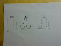
--- During the movement the strips of aluminum are changed as in the drawing (exaggerated for clarity), so you need a good elasticity along the strips.

--- The material that transversely joins the strips must be extremely flexible. The mylar, as well as being noisy, is not flexible enough though only 7 um thick.
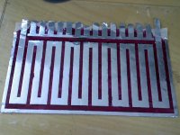
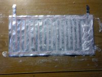
To meet the first point, of the various solutions I chose to use a modified design of the membrane as in the picture. The strips without Alu at the top and bottom ensure the necessary flexibility, being made with rubber, of which I will discuss below.

Having to make a part of the membrane with rubber might as well do it all. So I started to look for thin sheets of rubber. I not found them, but instead I found something better: a polyurethane elastomer liquid for casting with shore hardness 20A, that is very soft.
Long story short, after many failed attempts I learned to work with this polyurethane and a month later I produced a membrane passable.
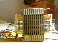
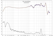
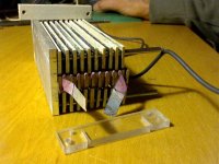
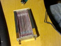
As engine I used 36 Neodymium magnets N38, 5 high, 10 wide and 25mm long, 120mm long strips of iron 3.8x10 spaced 3.8 with plexiglass, and I have a volume of the magnetic field of about 75x75x15mm. The simulation with magnetic designer gives me 0.23T in the field. Below the photo of the driver and one of the measurements made with REW, microphone 1cm away.


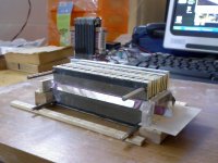
Then, forget the rules of sound, I made the mistake of listening to music with the driver as it is, resting on the table, and I immediately recalled the fundamental rule: lower frequencies = much larger dimensions, and it's taken me despair , so I'll have to radically rethink. Comments and suggestions are welcome.
Long follow several forums on the speakers esoteric, before the electrostatic, then ribbon and finally the AMT. I saw many wonderful accomplishments, and I congratulate all those involved.
A question came to my mind: Why the AMT do not arrive at low frequencies? Obviously it is a problem of compliance of the suspension, and after much thought and some tests have arrived at the following main conclusions:
--- During the movement the strips of aluminum are changed as in the drawing (exaggerated for clarity), so you need a good elasticity along the strips.
--- The material that transversely joins the strips must be extremely flexible. The mylar, as well as being noisy, is not flexible enough though only 7 um thick.
To meet the first point, of the various solutions I chose to use a modified design of the membrane as in the picture. The strips without Alu at the top and bottom ensure the necessary flexibility, being made with rubber, of which I will discuss below.
Having to make a part of the membrane with rubber might as well do it all. So I started to look for thin sheets of rubber. I not found them, but instead I found something better: a polyurethane elastomer liquid for casting with shore hardness 20A, that is very soft.
Long story short, after many failed attempts I learned to work with this polyurethane and a month later I produced a membrane passable.
As engine I used 36 Neodymium magnets N38, 5 high, 10 wide and 25mm long, 120mm long strips of iron 3.8x10 spaced 3.8 with plexiglass, and I have a volume of the magnetic field of about 75x75x15mm. The simulation with magnetic designer gives me 0.23T in the field. Below the photo of the driver and one of the measurements made with REW, microphone 1cm away.
Then, forget the rules of sound, I made the mistake of listening to music with the driver as it is, resting on the table, and I immediately recalled the fundamental rule: lower frequencies = much larger dimensions, and it's taken me despair , so I'll have to radically rethink. Comments and suggestions are welcome.
Attachments
Lupi, your diagrams depict an interesting aspect of AMT motion. I am not certain that the shape of the curve will be catenary like (as with a rope suspended between two points) While one side of a pleat is compressing air the other is creating a vacuum.
The inescapable reality is that the bottoms of the pleats enclose a volume of air that cannot be displaced because of the reduced motion. This "dead" air volume not only reduces the volume displacement but behaves like a sink for compressions or rarefactions that would otherwise propagate from the open sides of the pleats. This problem is not unique to AMT's, as moving coil woofers with large surround areas have similar problems. When the cone is moving backwards compressing air in the enclosure the surround can be ballooning outwards, partially cancelling what the cone is doing.
I am surprised that your AMT has output down below 50Hz. Did you have it on a large baffle or in a box? Presumably it would be almost inaudible at low frequencies. To generate usefull levels at low frequencies we need lots of volume displacement, meaning lots of motion and lots of membrane area.
If you read the Heil patents he proposed an AMT structure that used moving coil motors driving a number of flat diaphragms coupled with wire? carbon fibre? rods. A version that breifly appeared in the market place was called Transar. There is a modern version called a LAT, although, curiously, the manufacturer denies that it is an AMT.
You did very well with your first try.
Keith
I made the mistake of listening to music with the driver as it is, resting on the table, and I
immediately recalled the fundamental rule: lower frequencies = much larger dimensions
Nice work. Try it with a plywood etc. baffle so the rear wave doesn't cancel.
You may be more pleased then. Even so, you will have output level limitations.
I remember that ESS and Heil were continually "on the verge" of introducing an AMT woofer during the '80s. Showed some prototypes, but never actually produced one.
Competition for low frequency pleated foil-film AMT drivers....
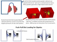
Push-Pull-Slot-Loaded speaker cabinets generate a high impact wave launch with a focused air pressure energy that travels several feet before diffusing. In a small room the slot is aimed at the listener in an effort to increase the perceived dynamic impact. A very good match for a horn midrange. At low SPL levels, the slot's focused energy wave is linear over a wide frequency range. At very high SPL levels, the high air pressures between the two drivers in the narrow slot can affect the perceived T/S parameters and create a non-linear response. The designer must manage slot volume vs. freq range vs. max SPL.
-->PPSL speaker cabinets use standard drivers to "spit-out" a compressed air wave. Same goal as AMT accordian folds.
=========
Ghost Busters 1 and 2 taught us: "Do Not Cross the Streams", "NEVER Cross the Streams".
(Ghost Busters 3 ..... Busty Girl Power Ghost Busters.... will be released in 2016)
With sealed woofers cabinets, one narrow single push-pull slot must deliver equalized high pressure low 20-80Hz bass in addition to voice-critical 100-250Hz. Sealed Slot loaded 20-250Hz crosses the streams! A narrow slot is required to avoid resonances anywhere near 250Hz, BUT a wide slot is required to avoid T/S parameter shifts from high air pressure 20-50Hz low bass.
--The high air pressure low bass in the narrow slot affects the sealed woofer's perceived T/S parmeters, and this modulates the ear sensitive midbass.
--The high air pressure low bass in the narrow slot competes with high-impact percussion impulses.
--Increasing the slot volume to accomodate the low bass pressures starts to reduce the directional high-impact percussion impulses.
--Moving the high pressure low bass energy out of the shared narrow slot into tuned ports avoids "crossing the streams".
Ported-Push-Pull-Slot-Loaded woofers can both cleanly "spit-out" a compressed midbass slot air wave, AND pump-out deep bass from tuned ports.
These ideas have been extended to dipole woofer construction. Linkwitz balanced W-frame, vs. narrow front slot frames.
Attachments
Keith, thanks response
--Whatever form it takes the strip of Al with the signal, very tough to stay straight, and absolutely no if has a constraint to the ends, even if it is elastic.
--It 'true that there is a dead volume, but I do not know if it have other negative effects as well as a reduction in yield. I have not yet addressed the issue. If you want we can look into.
---the fact that my test drops to 30 Hz, even with small dimensions, could show that the problem is the compliance of the suspensions. To provide sufficient volume to 30 Hz I did some accounts and have the intention (if developments are encouraging) to build an AMT capable of moving an air volume of 400 cm ^ 3 peak. They appear to be sufficient?
lupi
Rayma, thanks for encouragement. Certainly I try a baffle, and then I will consider a closed box. However my first realization should be only the first step
LineSource, Thanks for the answer and for the very clear explanation.
Very interesting these slots loaded speaker. I am now more oriented towards the driver with the mobile mass very small, even for low frequencies
Very interesting these slots loaded speaker. I am now more oriented towards the driver with the mobile mass very small, even for low frequencies
Rayma, thanks for encouragement. Certainly I try a baffle, and then I will consider a closed box.
However my first realization should be only the first step
Good luck, I've wondered why someone hasn't tried this for a woofer.
Hello everyone
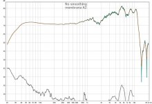
Before I install the driver on a baffle I had to seal some losses on attacks up and down of the membrane. Unfortunately during operation the membrane is gone and I had to build another. I built it using a method different from the previous, but the dimensions are the same: Aluminum: 15 um thickness, width 9 mm, 5 mm space, step folds 2.6mm. Total weight of the membrane 4.2 g, total size 27 x 13 cm. From the curve already it is understood that the thickness of the rubber came slightly higher, and therefore the corner frequency is around 45 Hz. The measurements with micrometer confirm.
measure 1_ A2.JPG
By varying the tension of the membrane the response does not change much, differently from what I had observed in previous experiences on other membranes, with which the corner could vary from 30 to 80Hz.
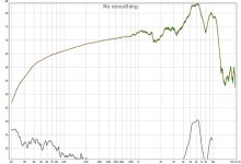
However proceeding to carry out other measures is something strange happened that still have not been able to explain, the response is changed as shown in Fig. following.
measure2_a2.jpg
I tried many things but the response is still the same, so I decided to build another membrane and repeat the same steps one at a time in order to identify the cause
Before I install the driver on a baffle I had to seal some losses on attacks up and down of the membrane. Unfortunately during operation the membrane is gone and I had to build another. I built it using a method different from the previous, but the dimensions are the same: Aluminum: 15 um thickness, width 9 mm, 5 mm space, step folds 2.6mm. Total weight of the membrane 4.2 g, total size 27 x 13 cm. From the curve already it is understood that the thickness of the rubber came slightly higher, and therefore the corner frequency is around 45 Hz. The measurements with micrometer confirm.
measure 1_ A2.JPG
By varying the tension of the membrane the response does not change much, differently from what I had observed in previous experiences on other membranes, with which the corner could vary from 30 to 80Hz.
However proceeding to carry out other measures is something strange happened that still have not been able to explain, the response is changed as shown in Fig. following.
measure2_a2.jpg
I tried many things but the response is still the same, so I decided to build another membrane and repeat the same steps one at a time in order to identify the cause
Attachments
I not found them, but instead I found something better: a polyurethane elastomer liquid for casting with shore hardness 20A, that is very soft.
Long story short, after many failed attempts I learned to work with this polyurethane and a month later I produced a membrane passable.
Would you like to share with us how you did it and the materials involded?
Lupi, are those measurements taken with the AMT on a baffle? What size is the baffle? In your second plot the AMT seems to be showing dipole loss at low frequencies.
This means that your front to back sealing around, or within, the AMT has failed. I am still amazed at how low in frequency this small AMT structure can go. Your rubber? pleat "creases" must be working some magic!
Keith
This means that your front to back sealing around, or within, the AMT has failed. I am still amazed at how low in frequency this small AMT structure can go. Your rubber? pleat "creases" must be working some magic!
Keith
LineSource, Thanks for the answer and for the very clear explanation.
Very interesting these slots loaded speaker. I am now more oriented towards the driver with the mobile mass very small, even for low frequencies
You can look up the slot loaded open baffle in Pass Labs threads.
http://www.firstwatt.com/pdf/art_slob.pdf
Oon
Certainly. I'm here to share.Would you like to share with us how you did it and the materials involded?
Of course the best method depends on the equipment you have. I have tried various methods but those that are successful are two.
1) chemical etching: lie down on a glass plate aluminum foil (with soap and water), prepare the surface with a very short etching with NaOH. Then we smear the polyurethane, brush or spray, the results are similar. After the polyurethane has cured completely I reverse the foil , rubber on the glass. Drawing the pattern, masquerade parties that I have to etch with adhesive tape, spray paint, take off the tape and dive all in the etching bath. I have tried both a solution of NAOH and of ferric chloride. The results are similar, but my impression is that NaOH alter a little the rubber. I take the foil and rinse thoroughly, and it is done
2) direct shear: I lie on a glass a sheet non-stick about100 um thick , then onto it the aluminum foil, always with soap and water, as it is done with the ribbon. I make a surfacial etching as above, then design the pattern and cut with a razor blade. On another glass lie another sheet of plastic anti-adhesive a little greater then the size of aluminum and there I brush the polyurethane. I wait about 10 minutes after the polyurethane has gelled but not cured, and put rubber down, on top of the aluminum foil carved. Wait 12-24 hours then I keep it one hour at about 60/80 ° C for complete cure. After, all still on the hot plate, take off the plastic sheets above and below the diaphragm and here.
Regarding the materials: aluminum is what you use in the kitchen, what I had is 15 um. The anti-adhesive plastic is that is used to line books and school notebooks, I think it is polyethylene, but not sure. Of course there are other materials: Teflon would be better, but is more expensive and a little more difficult to lie down. Polyurethane is PT FLEX 20 of POLYTEK and I bought it on the web.
Keith: that was the first well-sealed membrane. The two charts refer to the same membrane. For a few days I saw the response as in the first, then I did something I have not identified and had the second. Moreover even a prior membrane that had holes in the rubber gave a flat response. Keep in mind that the measures are with mic to 1 cm, then the back field has little influenceLupi, are those measurements taken with the AMT on a baffle? What size is the baffle? In your second plot the AMT seems to be showing dipole loss at low frequencies.
This means that your front to back sealing around, or within, the AMT has failed. I am still amazed at how low in frequency this small AMT structure can go. Your rubber? pleat "creases" must be working some magic!
Keith
Hello everyone.
To describe in more detail the manufacturing process, building the new membrane I took some pictures. I used the process of building with direct cutting.
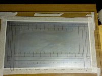
The first picture shows the glass sheet with on top the plastic sheet anti-adhesive and still above the aluminum foil, with the design of the pattern.
membA3 inizio.JPG
The etched surface gave varied color because that etching was not uniform, but for my purpose is fine. The darker areas are where the etching has been deeper, but it comes to tenths of um.
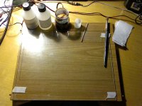
The second picture shows another glass plate with another plastic sheet anti-adhesive and drawed the edges of the area where I have to put the polyurethane. Above, from left to right are: The two components of the polyurethane, the solvent colored, a cup and a stick for mixing, a plastic spatula 0.3mm thick, made from a blister, the soft brush (if it was bigger would better) and cleaning paper.
setup x poliuret.JPG
The colored solvent is used to obtain a thinner layer, and is colored to more easily recognize the differences in thickness during the spread.
Before I calculate the volume of polyurethane that is need to have a thickness of 100um, then I add 1 cm ^ 3 to account for losses on the spatula and brush.
I pour in the cup the right amount of Part A, say 100 parts, then we add 50 parts of solvent and mix.
So far you can go quietly. Then add 80/90 parts of Part B (the data sheet says 100 parts of B, but I have found that it is better with less).
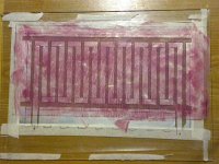
Now be quick: Mix everything completely (about 30 seconds) and pour on the area to be covered. With the spatula spread over the entire surface as more evenly is possible, then finish off with the brush. You have about 1-3 minutes available, the time depending on the temperature. As seen in the photo below, in this building I have not estimated well the time and temperature and the polyurethane has gelled while I was spreading, and then scratches of the spatula and the brush remained. If I was stopped 30 seconds before they would lay themselves.
This picture is at the left the layer just spreaded and at the right the cutted alu, and in 15 minutes I will combine the two.
This layer of rubber is the worse I make, but I will adjust it after peeling the plastic layers
membraA3.JPG
This other picture is of the layers just mated. I use a cylinder of 2 cm in diameter that I roll with a small pressure above all to remove the air bubbles and to adhere better.
To remove any air bubbles you can also go with your fingers, always with very light pressure.
After that, I put everything to rest with in top a layer of expanded rubber, then in top again a tablet and some weights to hold the whole stuff compact for 1 day.
membrA3.JPG
other result when I go ahead
To describe in more detail the manufacturing process, building the new membrane I took some pictures. I used the process of building with direct cutting.
The first picture shows the glass sheet with on top the plastic sheet anti-adhesive and still above the aluminum foil, with the design of the pattern.
membA3 inizio.JPG
The etched surface gave varied color because that etching was not uniform, but for my purpose is fine. The darker areas are where the etching has been deeper, but it comes to tenths of um.
The second picture shows another glass plate with another plastic sheet anti-adhesive and drawed the edges of the area where I have to put the polyurethane. Above, from left to right are: The two components of the polyurethane, the solvent colored, a cup and a stick for mixing, a plastic spatula 0.3mm thick, made from a blister, the soft brush (if it was bigger would better) and cleaning paper.
setup x poliuret.JPG
The colored solvent is used to obtain a thinner layer, and is colored to more easily recognize the differences in thickness during the spread.
Before I calculate the volume of polyurethane that is need to have a thickness of 100um, then I add 1 cm ^ 3 to account for losses on the spatula and brush.
I pour in the cup the right amount of Part A, say 100 parts, then we add 50 parts of solvent and mix.
So far you can go quietly. Then add 80/90 parts of Part B (the data sheet says 100 parts of B, but I have found that it is better with less).
Now be quick: Mix everything completely (about 30 seconds) and pour on the area to be covered. With the spatula spread over the entire surface as more evenly is possible, then finish off with the brush. You have about 1-3 minutes available, the time depending on the temperature. As seen in the photo below, in this building I have not estimated well the time and temperature and the polyurethane has gelled while I was spreading, and then scratches of the spatula and the brush remained. If I was stopped 30 seconds before they would lay themselves.
This picture is at the left the layer just spreaded and at the right the cutted alu, and in 15 minutes I will combine the two.
This layer of rubber is the worse I make, but I will adjust it after peeling the plastic layers
membraA3.JPG
This other picture is of the layers just mated. I use a cylinder of 2 cm in diameter that I roll with a small pressure above all to remove the air bubbles and to adhere better.
To remove any air bubbles you can also go with your fingers, always with very light pressure.
After that, I put everything to rest with in top a layer of expanded rubber, then in top again a tablet and some weights to hold the whole stuff compact for 1 day.
membrA3.JPG
other result when I go ahead
Attachments

Hello everyone.
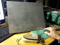
The last time I had obtained, above the glass sheet, a sandwich with 4 layers: 1) the plastic sheet 2) aluminum patterned 3) polyurethane rubber 4) plastic sheet. I waited one day for the rubber curing, then I put the sandwich on the hot plate. This is nothing more than an aluminum sheet of 2 mm thick put on an iron with thermostat modified to lower temperatures than normal.
I named this membrane A3
Heater & hot plate.JPG
After a couple of hours at about 60 ° C I tried to remove the top sheet of plastic, but I found that it was still too tight, in spite at the antisticking of plastic, so I waited another day and I tried again after 3 hours on the plate at 100 ° C. This time I was able to remove it, albeit with great difficulty. This rubber even after hardened attaches easily to all, especially to herself. If two edges of the membrane touch is very difficult to take off them without breaking anything. So after waiting for it to cool I sprinkled the surface with bath powder (talc).
membrane A3 powdering.JPG
Then I turned the remainder of sandwich, rubber bottom, and I pulled the other plastic sheet, which came off easily. I also put the powder on this face and I trimmed the edges. The total weight of the membrane is 4.11 g.
membrane A3 powdered.JPG
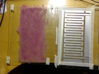
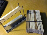
At this point I took out the tool to make the folds. This is a bad copy of the one described by Solhaga in the thread "yet another DIY AMT", post 54, with the difference that the strips used as thickness are shorter than the membrane by 4 mm, so I can glue the closures top and bottom . In the picture you can also seen the closure on the side of the electrical terminals, which has two slots for the passage of the strips of aluminum and 2 M2 threaded holes for attachment of the connections. Both closures have 3 mm holes for the screws with which I fix the sides of the frame.
pleating tool.JPG During pleating I used abundant dust on all to avoid that the membrane will attack to the thicknesses, which would be disastrous.
This is the pleated membrane.
membrane A3 pleated.JPG
And this is the membrane with the closures above and below glued.
membrane A3 end block glued.JPG
Before removing the thickness I attached the sides of the frame, which are two rectangular sticks of wood, of precise length, on one side of which I put double-sided tape to attach the flaps lateral ends of the membrane.
Then I very gently removed thickness helping me with a piece of thick paper to disconnect them. I put strip of adhesive rubber on the side closures of the frame so that all enter the magnetic field with slight friction. This is the end result.
membrane A3 finished.JPG
Soon I will perform the measures and post them
The last time I had obtained, above the glass sheet, a sandwich with 4 layers: 1) the plastic sheet 2) aluminum patterned 3) polyurethane rubber 4) plastic sheet. I waited one day for the rubber curing, then I put the sandwich on the hot plate. This is nothing more than an aluminum sheet of 2 mm thick put on an iron with thermostat modified to lower temperatures than normal.
I named this membrane A3
Heater & hot plate.JPG
After a couple of hours at about 60 ° C I tried to remove the top sheet of plastic, but I found that it was still too tight, in spite at the antisticking of plastic, so I waited another day and I tried again after 3 hours on the plate at 100 ° C. This time I was able to remove it, albeit with great difficulty. This rubber even after hardened attaches easily to all, especially to herself. If two edges of the membrane touch is very difficult to take off them without breaking anything. So after waiting for it to cool I sprinkled the surface with bath powder (talc).
membrane A3 powdering.JPG
Then I turned the remainder of sandwich, rubber bottom, and I pulled the other plastic sheet, which came off easily. I also put the powder on this face and I trimmed the edges. The total weight of the membrane is 4.11 g.
membrane A3 powdered.JPG
At this point I took out the tool to make the folds. This is a bad copy of the one described by Solhaga in the thread "yet another DIY AMT", post 54, with the difference that the strips used as thickness are shorter than the membrane by 4 mm, so I can glue the closures top and bottom . In the picture you can also seen the closure on the side of the electrical terminals, which has two slots for the passage of the strips of aluminum and 2 M2 threaded holes for attachment of the connections. Both closures have 3 mm holes for the screws with which I fix the sides of the frame.
pleating tool.JPG During pleating I used abundant dust on all to avoid that the membrane will attack to the thicknesses, which would be disastrous.
This is the pleated membrane.
membrane A3 pleated.JPG
And this is the membrane with the closures above and below glued.
membrane A3 end block glued.JPG
Before removing the thickness I attached the sides of the frame, which are two rectangular sticks of wood, of precise length, on one side of which I put double-sided tape to attach the flaps lateral ends of the membrane.
Then I very gently removed thickness helping me with a piece of thick paper to disconnect them. I put strip of adhesive rubber on the side closures of the frame so that all enter the magnetic field with slight friction. This is the end result.
membrane A3 finished.JPG
Soon I will perform the measures and post them
Attachments
-
 Heater & hot plate.JPG359.6 KB · Views: 165
 -
 membrane A3 powdering.JPG354.5 KB · Views: 147
 -
 membrane A3 powdered.JPG351.1 KB · Views: 148
 -
 pleating tool.JPG383.3 KB · Views: 170
 -
 membrane A3 pleated.JPG390.3 KB · Views: 205
 -
 membrane A3 end block glued.JPG369.5 KB · Views: 198
 -
 membrane A3 finished.JPG375.2 KB · Views: 194
- Status
- Not open for further replies.
- Home
- Loudspeakers
- Planars & Exotics
- An AMT for low frequencies