I have some K1530/J201 I bought long time ago (supposedly matched but not sure how well). I also have some K2013/J313 as well as some papa's j favorites 170/74. I have been mulling putting all of these to a good use.
While sort of keeping an eye on what amp could use these I seem to have missed a nice pointer from Papa himself that the front end of the Sony VFET 2 could drive these nicely.
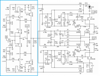
Please check out the Vfet front end schematic and Papa's comments. I am far from an expert: it sounds to me the FE could be used to drive something like an F4 output stage? just drop the buffer. Did I get that wrong?
Could maybe someone draw up or sim what this should look like with say 2 (or 3) pairs of K1530/J201 per channel and which values would need adjustment? maybe estimate a few starting values if the rails were at +/-28V shared with the FE? Thanks a lot. Your help is much appreciated.


also please feel free to post in this thread other amps which make use of the Toshiba parts.
p.s. I am also hoping Papa gets bored one afternoon (probably no chance with everything else going on right now but eventually), and finishes his thought with a nice schematic; sort of "a tribute to Toshiba" even though the parts are conventional in comparison to Sony prima donnas 😉.
While sort of keeping an eye on what amp could use these I seem to have missed a nice pointer from Papa himself that the front end of the Sony VFET 2 could drive these nicely.
Please check out the Vfet front end schematic and Papa's comments. I am far from an expert: it sounds to me the FE could be used to drive something like an F4 output stage? just drop the buffer. Did I get that wrong?
Could maybe someone draw up or sim what this should look like with say 2 (or 3) pairs of K1530/J201 per channel and which values would need adjustment? maybe estimate a few starting values if the rails were at +/-28V shared with the FE? Thanks a lot. Your help is much appreciated.


also please feel free to post in this thread other amps which make use of the Toshiba parts.
p.s. I am also hoping Papa gets bored one afternoon (probably no chance with everything else going on right now but eventually), and finishes his thought with a nice schematic; sort of "a tribute to Toshiba" even though the parts are conventional in comparison to Sony prima donnas 😉.
Last edited:
nope
sleep is overrated
going back to bed, some reading and see ya in late morning
woke up, was thirsty ( too much peanuts before sleeping) but main reason was that I woke up having urge to write down something
though, can't remember what, but I know it will dive out these days
sleep is overrated
going back to bed, some reading and see ya in late morning

woke up, was thirsty ( too much peanuts before sleeping) but main reason was that I woke up having urge to write down something
though, can't remember what, but I know it will dive out these days
Perhaps not what you’re after, but I recently built an F5 with K1530/J201‘s and K170/J74’s in the FE. Definitely an all Toshiba amp, and it’s become one of my favorites. You could even do a Turbo if you wanted more power.
Nonetheless, I’ll be excited if a new design emerges that uses these parts. They’re fantastic!
Nonetheless, I’ll be excited if a new design emerges that uses these parts. They’re fantastic!
you Silly
that's BA3 FE
now that you mentioned it does look familiar (and I already have BA-3b mono blocks with F4 OS). how funny is that? 😀 not sure what Q13/14 are in the Vfet FE though and the rest of the fine differences.
well if not far enough we can always go looking for something different. I know indra may be making something more novel soon where I may use a tube in the FE (worst case but definitely different).
Last edited:
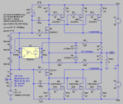
If you don't mind an input coupling capacitor, I have CFP Toshiba MOSFET @ 28V biased M2 style in archive, similar to a Stasis OS but with MOSFETs.Could maybe someone draw up or sim what this should look like with say 2 (or 3) pairs of K1530/J201 per channel and which values would need adjustment? maybe estimate a few starting values if the rails were at +/-28V shared with the FE?
- 40W into 8 ohm, 75W into 4 ohm.
- Very low ppm level distortion.
- Damping factor 664, 12 miliohm output impedance.
Log file @ 1W into 8 ohm load:
Code:
N-Period=all
Fourier components of V(out)
DC component:-0.00186744

Harmonic	Frequency	 Fourier 	Normalized	 Phase  	Normalized
 Number 	  [Hz]   	Component	 Component	[degree]	Phase [deg]
    1   	1.000e+03	4.000e+00	1.000e+00	    0.02°	    0.00°
    2   	2.000e+03	2.871e-05	7.177e-06	   45.58°	   45.56°
    3   	3.000e+03	6.726e-07	1.682e-07	   -0.61°	   -0.63°
    4   	4.000e+03	6.676e-07	1.669e-07	 -176.37°	 -176.38°
    5   	5.000e+03	5.100e-07	1.275e-07	 -179.74°	 -179.76°
    6   	6.000e+03	4.236e-07	1.059e-07	 -179.99°	 -180.01°
    7   	7.000e+03	3.645e-07	9.113e-08	 -179.97°	 -179.99°
    8   	8.000e+03	3.180e-07	7.951e-08	 -179.93°	 -179.95°
    9   	9.000e+03	2.823e-07	7.059e-08	 -179.93°	 -179.95°
Total Harmonic Distortion: 0.000718%(0.002688%)C4 and C5 are needed to ensure HF stability, but smaller 39pF - 82pF can be used.
LTspice asc and associated include files are zipped together.
Posted in SERFE - a Single Ended Rush Pair Front End. Please note Attachment #4,6,7 of the first post.... indra may be making something ...
One of my business acquaintance has thousands of 2SJ103GR in stock, I'll be happy to send you a few matched pairs in case you have difficulties in getting them. The 2SJ103 can be substituted with LSJ74 but then you may need to compensate for HF stability.
Attachments
Now we are talking. Thanks Indra. I will look over all the info.
Hopefully this thread turns into a repository for all schematics which use Toshiba parts. Not necessarily an "all Toshiba amp" as in the title since that may be too prohibitive but with other parts too that can help them shine.
As for F5 mentioned above: I already have it with the IR parts and do not feel like changing the devices only (well maybe eventually; the footprint does not fit the board and more holes in the hsink would be required). But this amp is apparently one of the best applications for K1530/J201. Here is what Nelson commented at one point:
https://www.diyaudio.com/forums/pass-labs/313569-baffle-spend-toshiba-2sj201-sk1530.html#post5215161
The only mods I made to the F5 were to decrease feedback (100R to 200R) and reduce degeneration resistance. I’ve been meaning to try it without degeneration entirely, but haven’t had the time. It’s nothing new, but it can be considered a safe bet.
I have built my M2 as an all Toshiba amp ... 2SJ201 and 2SK1530 in the output stage, and 2SJ74/2SK170 input.
Only changes to attached schematic are (following guidance by Zen Mod and Generg):
- change source resistors R13/R14 to 0R33
- replace R11 from 221R to 0R (jumper) to bring bias down again after reducing source resistors had raised bias
My M2 runs at +- 24V rails and 1.8A bias 😀
Regards, Claas
Only changes to attached schematic are (following guidance by Zen Mod and Generg):
- change source resistors R13/R14 to 0R33
- replace R11 from 221R to 0R (jumper) to bring bias down again after reducing source resistors had raised bias
My M2 runs at +- 24V rails and 1.8A bias 😀
Regards, Claas
Attachments
- Home
- Amplifiers
- Pass Labs
- an all Toshiba amp after Papa's hint


