I don't understand how a bad TL072 could cause the voltage on pin 2 of the 21844 to be low without pin 7 of the LM293 (or whatever they're using) being high.
Do you have signal reaching the driver board when the amp does as shown in the photos?
What frequency test signal are you using?
Do you have signal reaching the driver board when the amp does as shown in the photos?
What frequency test signal are you using?
Replacing the max transistors took care of the issue on pin 2.
The strange modulation was from the tl072.
I'm assuming it's getting signal. When I take the fets out the signal is perfect
The strange modulation was from the tl072.
I'm assuming it's getting signal. When I take the fets out the signal is perfect
You don't have to remove the FETs. All you have to do is bridge pins 2 and 3. That will shut down the 21844s.
When the FETs were in the board and you were driving a signal into the amp (frequency?) and you did not get rail-rail oscillation, how far did the drive signal get?
Output of the TL072?
Output of the LM211?
Input of the 21844?
Output of the 21844?
Do you have a signal generator that can generate a triangle waveform at approximately 100kHz?
Pulled this amp back out for another go at it.
The output section is separated from the ps for safer low voltage testing. +/- 20vdc on the rails
This amp uses the ZNCM_HP style driver card
My question is, how important is the duty cycle on the output section at idle? I have 3 different driver cards for this amp that all work in another amp and they all behave differently with drastically different duty cycles.
This is all without fets in. As soon as the rail to rail starts the amp draws current and the fets heat up when they are in.
Were you testing these boards in the other amps like you're testing in this amp?
Duty cycle can't be 'normal' if the entire feedback loop isn't complete.
Do you have a square wave generator?
Duty cycle can't be 'normal' if the entire feedback loop isn't complete.
Do you have a square wave generator?
No but since they work fine in another amp I think I'm chasing a non issue.
I don't get it. Without the fets everything seems fine.
I don't get it. Without the fets everything seems fine.
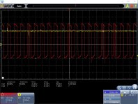
Yep. It will start switching R2R with the fets in but it starts squealing and draws current causing the fets heat up.
Last edited:
Do ALL of the FETs heat up at the same rate when you have the FETs in the amp?
Did you confirm that the driver ICs had a good 12v supply for the low-side drive section?
What are you using for the ±20v supply?
Did you confirm that the driver ICs had a good 12v supply for the low-side drive section?
What are you using for the ±20v supply?
So here's what's weird.
Depending on which card I have in the fets that heat up the most change.
For some reason today i can only get 1 of the cards to actually stay switching. Last night all 3 worked. I haven't touched it since.
And all 3 still work fine in a different amp.
With the card I can get to work now. 1 high side and the opposite low side heat up the most.
Another thing that isn't making sense is initially all rail voltages are correct the amp tries to start switching then shuts down. The moment it shuts down I get full neg rail on the center leg of the high side
Also it's starts switching well before the rail voltage is built.

You'd feel right at home in my shop.
What are you using to get drive pulses to the output FETs?
What frequency?
Do you have any capacitors in the range of 0.001uf and 0.01uf?
What are you using to get drive pulses to the output FETs?
What frequency?
Do you have any capacitors in the range of 0.001uf and 0.01uf?

I usually drive a 50hz wave for testing but it starts switching without signal.
Yes I have a .01uf cap
Yes I have a .01uf cap
Does the 50Hz signal produce the square wave at the output FETs?
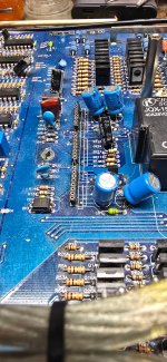
Post a photo of the main board in the area of the driver board and output locations.
Post a photo of the main board in the area of the driver board and output locations.

I was asking about signal at the gates of the output FETs. Are you saying that you don't get signal on the gates of the FETs when the FETs are installed?
Drop some FETs into one side. It can be a single FET in each bank. The FETs don't need to be the originals. They can even be PS FETs. Does that side oscillate normally?
For your ±20v supply, you may want to install some limiters in the output lines. 20v is a bit too high for 12v lamps. If you have some halogen lamps (long, cylindrical), they would work and wouldn't take up much space.
For your ±20v supply, you may want to install some limiters in the output lines. 20v is a bit too high for 12v lamps. If you have some halogen lamps (long, cylindrical), they would work and wouldn't take up much space.
- Home
- General Interest
- Car Audio
- Ampre Audio 7.5k