hi Junm
i,m sure Antoinel will have an answer for you on that ,it depends on the bias current
I usually only build class a stuff but I know these vfets can sound sweet in a or Ab so I,m not too fussed
Sheafer
i,m sure Antoinel will have an answer for you on that ,it depends on the bias current
I usually only build class a stuff but I know these vfets can sound sweet in a or Ab so I,m not too fussed
Sheafer
Last edited:
Junm and sir 5000. The amp is most probably operating in Class A.hi Junm
i,m sure Antoinel will have an answer for you on that ,it depends on the bias current
I usually only build class a stuff but I know these vfets can sound sweet in a or Ab so I,m not too fussed
Sheafer
Best regards.
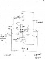
There are two trimmer [variable] resistors in the BA3 front end circuit at the drains of 2SJ/2SK complementary JFETs. They adjust the idle current of the complementary MOSFETs [in BA3 FE]. This idle current passing through a suitable resistor at the drain of each MOSFET then generates an adjustable voltage drop or bias voltage [Vgs] to each VFET.thanks antoinel, maybe we can put trimmer resistor somewhere to vary the bias....any idea?
sir 5000. The attached schematic is your proposed idea above to use BA3 FE.
It'll work. Initially include 0.5A fast blow fuses in the drain circuits of the VFEts as an essential precaution. Energize the front end first to establish bias to the VFETs, and then turn on the power supply to the VFETs.
- The overal amp now inverts phase. If needed, loop feedback returns to the joined gates of SJ/SK JFETs.
- The value of Rb multipled by the idle current of BA3 output stage is the bias to the VFETs.
- The ratio of Rb to Ra is a gain factor.
- If one did not include the bjt buffers in the Amplimos FE, a similar situation arises as above; except there is signal phase inversion. The new Amplimos overal amp is still non inverting. If needed, loop feedback returns to the joined sources of the SK/SJ JFETs; like in F5 for example.
- There's got to be an operational value to using the bjt buffers. What is the input capacitance of the VFEts?
Antoinel,
In your schematic you don't deal with the bias of these devises at all.
How do you propose to supply the bias to these depletion mode devises?
Fuses in the drain are not a great idea because if one blows you could end up with rail DC voltage on you speaker. Better to bring the voltage up slowly with a variac.
Zen Mod showed a schematic and biasing for an F6 using these devises in the F6 thread, your amp should follow the biasing pretty closely, I guess.
http://www.diyaudio.com/forums/pass-labs/216616-f6-amplifier-344.html#post3323995
and here: http://www.diyaudio.com/forums/pass-labs/216616-f6-amplifier-345.html#post3325340
I am glad to see you have your soldering iron out. How is your experiment with 317/337 devises? No one responded to the post you referred to in the F6 thread (727), so don't really know if you can use these as output devises in a power amp. You have come up with a lot of ideas in the past, but I haven't seen your implementation.
Look forward to your progress and let us know how the experiments are going.
Rush
Thank you for the underlined in your post.
- The schematic of Zen Mod in the F6 Amplifier thread is highly detailed. This suggests he already assembled it and knows that it performs; which I also believe.
- Always prudent to use a variac when starting a new circuit. I practice it all the time; fearing to replace power output transistors.
- The front end of BA3 has variable resistors in both drain circuits of the complementary JFETs; to be used to adjust the bias of the depletion FETs via the variable voltage drops across the bias resistors in the drain circuit of the BA3 FE MOSFETs.
- I have ideas. Some are hot, while others are hot air. This thread started with an idea by sir 5000; which is his vision of a concept amp. Each of us brings to the DIY bench a different offering and perspective. I cherish all.
- Thank you for the kick in the hind regarding the status of LM317/337 as depletion-style power output devices. It is my pleasure to update you and interested others [today] about its progress in an upcoming post.
Thank you for the underlined in your post.
- The schematic of Zen Mod in the F6 Amplifier thread is highly detailed. This suggests he already assembled it and knows that it performs; which I also believe. Zen Mod has not built that schematic, he just drew the schematic for our use.
- The front end of BA3 has variable resistors in both drain circuits of the complementary JFETs; to be used to adjust the bias of the depletion FETs via the variable voltage drops across the bias resistors in the drain circuit of the BA3 FE MOSFETs. You need a negative bias voltage to turn the "N" devise off, at zero voltage the 2SK82 is full on. You can't do that with BA3 front end, without injecting a negative voltage, like Zen Mod has drawn. Same goes for the "P" devise needs a positive bias voltage to turn it off. So you need 2 separate bias supplies (-/+).
Best regards
I am not sure how to accomplish this with a BA3 front end, so I look forward to seeing this thread progress.
Rush
Posts 7 and 17 have the simplified schematic and biasing details. Progress is in the hands of sir 5000.I am not sure how to accomplish this with a BA3 front end, so I look forward to seeing this thread progress.
Rush
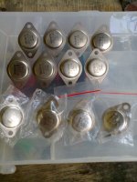
Rush and Sheafer. Circlomanen was right about his idea to use LM317 and LM337 variable voltage regulators as Depletion devices. The schematic and pictures of the working prototype driving L300C ADS speakers are attached. Sounds great; regarding the clarity of the high end and the overall spectral balance. Time after Time, and Cracklin' Rosie were the test CD tunes. I'll further characterize it and report findings in a dedicated thread.Hi Sheafer. DIYer Circlomanen wrote in Post #727 of the F6 Amplifier thread aboutr using LM317/337 as complementary depletion devices. I did not read the follow up on his suggestion of trialing them. I will use them initially to build confidence as a prudent measure before using the scarce VFETs.
Best regards
Best regards.
Attachments
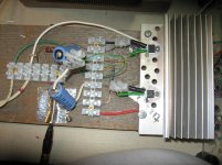
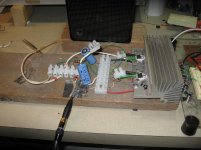
Rush and Sheafer. Circlomanen was right about his idea to use LM317 and LM337 variable voltage regulators as Depletion devices. The schematic and pictures of the working prototype driving L300C ADS speakers are attached. Sounds great; regarding the clarity of the high end and the overall spectral balance. Time after Time, and Cracklin' Rosie were the test CD tunes. I'll further characterize it and report findings in a dedicated thread.
Best regards.
Nice work.
So you set it up self bias like a tube. Was there any dc offset?
Link us to your thread when you start it.
Rush
Thanks Rush. ~2 mV DC offset across the loudspeaker. The idle bias current per device is 120 mA. I'll keep you connected.Nice work.
So you set it up self bias like a tube. Was there any dc offset?
Link us to your thread when you start it.
Rush
Best regards
Sorry for necrobumping this old thread...
I have a box full of THF-51 and was looking for schematics. I was mostly looking for push-pull configurations, found the Amplimos circuits, and then stumbled over this thread.
The Amplimos circuits do not seem to have any trim pots or similar means to adjust bias/operating points or the DC offset (example: V-FET SIT Amplimos ). I was wondering if/how those who built the Amplimos designs tweaked their builds to get the desired bias and zero DC offset.
Any thoughts on this?
- Home
- Amplifiers
- Solid State
- Amplimos 2sk82/28 push pull build thread