I guys
I have some sony 2sk82/2sj28 sitting around doing nothing and have decided to try one of the schematics on the Amplimos site
I have permission from the owner Francesco to try to get some boards made and a few circuit recommendations so we are good to go
I hope others will join in along the way as I think these parts have a lot of potential and are still easy to get (expensive though)
any interest please chime in
below is the circuit of interest
http://www.amplimos.it/images/V-fet complementary 2SK82_2SJ28_Ver_B.bmp
Sheafer
I'll keep an eye on your interesting thread.I guys
I have some sony 2sk82/2sj28 sitting around doing nothing and have decided to try one of the schematics on the Amplimos site
I have permission from the owner Francesco to try to get some boards made and a few circuit recommendations so we are good to go
I hope others will join in along the way as I think these parts have a lot of potential and are still easy to get (expensive though)
any interest please chime in
below is the circuit of interest
http://www.amplimos.it/images/V-fet complementary 2SK82_2SJ28_Ver_B.bmp
Sheafer
hi all
Ok so the first step I suppose is to make some boards and being a total noob in this area I,m not sure where to start
So I have downloaded eagle and am in the process of trying to understand what it can do
now I,m hoping there is a way to simply import the schematic I have but I will need some help so any of you guys out there that know this program I would love some advice
Sheafer
hi all
Ok so the first step I suppose is to make some boards and being a total noob in this area I,m not sure where to start
So I have downloaded eagle and am in the process of trying to understand what it can do
now I,m hoping there is a way to simply import the schematic I have but I will need some help so any of you guys out there that know this program I would love some advice
Sheafer
Here is a light analysis of the amplifier's schematic shown in post#1.
- Uses two power supplies. A +/- 40 V for the low level and low power front end, and another solely dedicated to the VFET output stage.
- It is imperative that Vgs to the power VFETs be applied before their Vds. So the +/- 40 V power supply is expected to be left on continuously so as to satisfy this requirement.
- The package of the driver bjts are TO-92 MOD of maximum power dissipation of 750 mW.
- Assuming Vgs for each Vfet = 6V, the joined emitter current of the bjt is ~6 mA; well within SOA.
- The bjts [buffers] bias the output stage, and supply input signals to the VFETs which operate in common source configuration; meaning they produce power gain, and invert the phase of the input signals at their gate.
- The input to this amp is the classical complementary depletion JFETs found in FirstWatt amps; e.g. BA3 front end, and F5. As shown, the input signal is amplified and its phase inverted at the drain ports.
- The gain stage which follows is a complementary pair of JFETs connected in common gate configuration. This stage references to signal ground the output signals of the first stage, and does not invert phase.
- The complementary bjts are configured common collector; meaning buffers, and do not invert the phase of the signal presented to their bases.
- The totallity of the amp does not invert the signal phase presented at its input.
- The VFET ouput stage lacks negative feedback. Ditto for the low level/power circuit driviving the VFETs,
Best regards
I guys
I have some sony 2sk82/2sj28 sitting around doing nothing
You received some very good tips in this thread; ilimzn is quite knowledgeable when it comes to these devices.
hi all
thanks for the circuit analysis Antoinel
from your description above I,m thinking that something like the ba3 front end could be used here with the output stage in the amplimos schematic ,
this would mean a quick build on the front end and the output stage could be done point to point
am I correct in this assumption ?(or wrong as usual😱)
hi yamahear
yes I can tell ilimnz is very knowledgeable with these devices and I plan on using his suggestions ,I have ditched the idea of adapting the hiraga circuit because of this
Sheafer
Last edited:
hi all
thanks for the circuit analysis Antoinel
from your description above I,m thinking that something like the ba3 front end could be used here with the output stage in the amplimos schematic ,
this would mean a quick build on the front end and the output stage could be done point to point
am I correct in this assumption ?(or wrong as usual😱)
hi yamahear
yes I can tell ilimnz is very knowledgeable with these devices and I plan on using his suggestions ,I have ditched the idea of adapting the hiraga circuit because of this
Sheafer
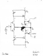
sir 5000. The attached schematic is your proposed idea above to use BA3 FE.
- The overal amp now inverts phase. If needed, loop feedback returns to the joined gates of SJ/SK JFETs.
- The value of Rb multipled by the idle current of BA3 output stage is the bias to the VFETs.
- The ratio of Rb to Ra is a gain factor.
- If one did not include the bjt buffers in the Amplimos FE, a similar situation arises as above; except there is signal phase inversion. The new Amplimos overal amp is still non inverting. If needed, loop feedback returns to the joined sources of the SK/SJ JFETs; like in F5 for example.
- There's got to be an operational value to using the bjt buffers. What is the input capacitance of the VFEts?
Attachments
Antoinel you are the best
I cant emphasize enough how much I value your help
I will order the ba3 front end boards now and start organizing the heatsinks ect
I have a few transformers here already that I,m hoping to use
I have 2 x rcore 300va 18v/18v
2 x toroid 500 va potted 25/25v
2 x toroid 625 va 55v/55v
2 x toroid 300va 18v/18v
cheers Sheafer
this thread section mentions the input capacitance
http://www.diyaudio.com/forums/pass-labs/192665-2sk82-lightbulbs-fun-2.html
Last edited:
Thanks. The input capacitance of 2SK82 is quoted at 4000pF; which may explain using bjt buffers in the Amplimos front end. By comparison, what is input capacitance of the power stage of BA3 amp?Antoinel you are the best
I cant emphasize enough how much I value your help
I will order the ba3 front end boards now and start organizing the heatsinks ect
I have a few transformers here already that I,m hoping to use
I have 2 x rcore 300va 18v/18v
2 x toroid 500 va potted 25/25v
2 x toroid 625 va 55v/55v
2 x toroid 300va 18v/18v
cheers Sheafer
this thread section mentions the input capacitance
http://www.diyaudio.com/forums/pass-labs/192665-2sk82-lightbulbs-fun-2.html
I am cautious, and suggest using a 300VA transformer. Most important is to assemble the power supply of the output stage exactly like in the Amplimos schematic. I think Corrado used delays in Vds [high value smoothing caps] and Idss [inductance of transformer] so as to further protect the VFETs. By comparison, the light bulbs and inductor loads in Rothacher SIT amps aid in protecting the SIT from an inadvertent inrush of destructive Idss.
Best regards
Sorry for the OT Sheafer, but do you happen to have a Torana? (non Aussies will be saying what the...?).
Hi Stuey
yes but I sold her last year
an azure blue lh slr 5000
I,m now doing up a reef green xw gt mockup with a 393 clevo
cheers Sheafer
yes but I sold her last year
an azure blue lh slr 5000
I,m now doing up a reef green xw gt mockup with a 393 clevo
cheers Sheafer
hi Antoinel
I have the ba3 frontend boards on their way and will place an order for the output stage parts as per the amplimos schematic
in the meantime I will mess around with the f4 I already have built and almost ready to fire ,I will try the ba3 frontend on this whilst I,m building the amplimos output stage and case
Sheafer
Hi Stuey
yes but I sold her last year
an azure blue lh slr 5000
I,m now doing up a reef green xw gt mockup with a 393 clevo
cheers Sheafer
Cheers. Thought the moniker couldn't mean anything else. Unusual to 'change sides' though! 😉
hi Stuey
true , but I started on the other side so ive come home
I,m not satisfied unless I can fit my hand in the intake ports to feel the curves 😀
true , but I started on the other side so ive come home
I,m not satisfied unless I can fit my hand in the intake ports to feel the curves 😀
Hello sir 5000. Glad you are enthused about this diy project, and I look forward to your progress. I have BA3 FE pcbs from our diyAudio store. I'll examine one today to understand fitting the new schematic. The store has also pictures of it for your analysis.hi Antoinel
I have the ba3 frontend boards on their way and will place an order for the output stage parts as per the amplimos schematic
in the meantime I will mess around with the f4 I already have built and almost ready to fire ,I will try the ba3 frontend on this whilst I,m building the amplimos output stage and case
Sheafer
Best regards.
sir 5000. I examined the BA3 FE [stereo] pcb which is double-sided. There is room to insert the 2 load resistors [Rb] for the output MOSFETs per the revised schematic. Components C3 and R12 are not needed, and leave valuable empty space. R13 will be substituted by the 2 load resistors which need to be rated a minimum 1/2 W. For 6 V Vgs, I calculate Rb=130 Ohms each dissipating ~0.3 W due to 45 mA current flowing through them. Delicate drilling, scraping of the trace protection film, and parting the trace of the joined MOSFET drains are all feasible. The above description is also clear in the picture of the pcb in the store forum.Hello sir 5000. Glad you are enthused about this diy project, and I look forward to your progress. I have BA3 FE pcbs from our diyAudio store. I'll examine one today to understand fitting the new schematic. The store has also pictures of it for your analysis.
Best regards.
Good luck and best regards.
hi Antoinel
I just ordered all the parts to populate the ba3 fe tonight so I should be good to go within a week
I think with the ba3 frontend and these vfets this will be an awesome amplifier
thanks to you again
will you be trying the circuit ?
regards Sheafer
I just ordered all the parts to populate the ba3 fe tonight so I should be good to go within a week
I think with the ba3 frontend and these vfets this will be an awesome amplifier
thanks to you again
will you be trying the circuit ?
regards Sheafer
Hello Sheafer. I will assemble the FE on a protoboard. I do not have VFETs. A DIYer suggested [in F6 amplifier thread] using the adjustable voltage regulators LM317/337 as complementary depletion devices. I expect to use them and/or L'Fake SITs per the teaching of wrenchone as learning tools. I'll post the findings as I go along.hi Antoinel
I just ordered all the parts to populate the ba3 fe tonight so I should be good to go within a week
I think with the ba3 frontend and these vfets this will be an awesome amplifier
thanks to you again
will you be trying the circuit ?
regards Sheafer
Best regards.
Hi Sheafer. DIYer Circlomanen wrote in Post #727 of the F6 Amplifier thread aboutr using LM317/337 as complementary depletion devices. I did not read the follow up on his suggestion of trialing them. I will use them initially to build confidence as a prudent measure before using the scarce VFETs.Hello Sheafer. I will assemble the FE on a protoboard. I do not have VFETs. A DIYer suggested [in F6 amplifier thread] using the adjustable voltage regulators LM317/337 as complementary depletion devices. I expect to use them and/or L'Fake SITs per the teaching of wrenchone as learning tools. I'll post the findings as I go along.
Best regards.
Best regards
- Home
- Amplifiers
- Solid State
- Amplimos 2sk82/28 push pull build thread