Hi,
I am setting up system whereby a computer programme generates a series of square pulses that are then outputted via USB and a data acquisition module at a voltage of up to 5V (I think, via USB?).
I need to amplify this square pulse to by about 5-10 times to give a final voltage of up to 50-70V and my current set-up is using a normal home audio amplifier (made by NAD).
I have tested the output signal both before and after amplification and whilst the original signal from the DAQ module is square and of the right voltage, the amplified pulses are not, the voltage for each pulse drops during the pulse (so each pulse slopes down a bit). I have been told that this is due to the amplification so I wondered if anyone had any suggestion as to why this might be happening?
Some suggestions I have had so far include putting in an 8 Ohm resistor to provide the same resistance as if the amp were connected to speakers, and also that I need a dc-dc amplifier instead of a dc-ac amplifier. I have also been told that amplifying a square wave can be problematic - is this the kind of problem that arises from trying to amplify a square pulse?
Can anyone point me in the right direction to solve this problem? I am new to this area and would really like to be able to get this sorted out as I need my pulses to be square.
Thanks for any advice🙂
The voltage droop is from the audio amplifier. Their band is typically 10Hz to 20kHz, they do not amplify from 0Hz.
You need another amplifier for DC. A 0Hz to ??Hz amp.
To help you about such an amplifier we need to know:
_The load
_The levels.
_The required accuracy for the shape of the pulse(s). The turn on time and turn off time, the on and off durations, the droops.
You need another amplifier for DC. A 0Hz to ??Hz amp.
To help you about such an amplifier we need to know:
_The load
_The levels.
_The required accuracy for the shape of the pulse(s). The turn on time and turn off time, the on and off durations, the droops.
A square wave is made up of the fundamental frequency plus reduced odd higher harmonics. You need to amplify pulses that go from 0 volts to +5volts? If you are using single positive or negative pulses you will have to have a DC coupled amplifier. You will need an amplifier that has a bandwidth at least 10 times of your pluse fundamental to get something that looks like the original. If your desired output is pulses in the 50-70 volt peak range the amplifier will have to have a power supply that is around 5-10 volts higher than your desired output. To sumarize you need a DC coupled amplifier with a power supply of about + /- 80 volts and a bandwidth of 10 x your pluse fundamntal frequency. If you pluse width is 1 millisecond then the frequency would be around 500 hz. Providing of course that the next pluse does not occur in time less that the pluse width. ie 1 millisec pluse, 1 micro sec delay then another 1 millesecond pulse, then in that case the frequency is 500 khz and the bandwidth needed is 5 mhz. Not a cheap amplifier and not a stereo for sure.
Please answer post #2, and I agree: i don't think it is a task for an audio amplifier. Maybe all you need is a switch (MOSFET) with a 70 V supply.....
Assuming digital pulses are being fed to an audio amp you aren't going to get nice clean square waves. There is capacitive coupling at the input and feedback path of a typical amplifier which will impair the shape of the square wave. This will be frequency dependant. Also, If the input signal is varying from 0v to 5v, you are gradually putting a DC charge on these capacitors which will upset the amplifier.
Perhaps a simpler direct coupled approach with some MOSFETs and a suitable supply might work better. What frequency range are you operating in and might I ask the application?
Perhaps a simpler direct coupled approach with some MOSFETs and a suitable supply might work better. What frequency range are you operating in and might I ask the application?
It sounds like what you really need is to not use the computer to generate the actual waveform.. rather to program some DDS synthesis which then drives a dedicated output stage
Hi guys,
Wow, thanks for much for your replies to my query, really appreciated! I will try to answer everyones questions but I must apologize for my lack of understanding in this area, I am a biochemist by trade and finding the electronics/amplifiers side of things a very steep learning curve!
Here goes...
mchambin: I am not sure what the actual load is, the voltage has to pass through the electrodes and then through a liquid and so I guess the resistance will be quite high? I will try to measure it later on if I can.
I have been told that the pulses need to be square to allow consistent delivery of the right voltage for a short defined period each time. I understand it isn't possible to have an instant on-off for the pulse, but I'm afraid I don't know exactly what the required on-off times should be - I think the important thing is that the plateau at the top of the wave should be level i.e. not drooping, so that the voltage is constant for the pulse width that we set.
I'm not sure what you mean by levels? (Sorry)
multisync: Yes I am amplifying the square wave pulses that start at 0V and then go up to +5V (or whatever amplitude I set on the software between 0 and 5. I am also looking to generate bipolar pulses to avoid salt build up on the electrodes but that's another story!
The delay between the pulses will vary - at the moment the pulse width is about 4ms and the frequency is 20Hz so that gives about 45ms between pulses I think? The maximum frequency of the pulse train will be about 100Hz so I guess the delay between pulses will be approaching the width of the pulse but not less than it.
jkeutemann: The application is for a scientific research project involving muscle research - I know it sounds a bit Frankenstein but it's not, honest! 🙂 It's for an artificial system looking at muscle stimulation. I am actually trying to set up a system similar to one from some colleagues in the US where they have used a DC-DC MOSFET audio power amp to do the same job, but I can't seem to track down a similar model that will work in the UK hence my queries on this.
The frequencies we are generating are pulse trains of 20Hz to about 100Hz maximum - I'm not sure if this is the frequency range you are referring to? I am getting a little confused between the frequencies of the square waves themselves and the frequencies of the train of square pulses I am creating!
jaycee and cbdb: Unfortunately I need to use this software and the computer to generate the original signal at this stage as it is also going to be coupled in to some other equipment to measure other parameters from the same system. So the main aspect is the amplification itself at the moment. But I have seen similar things set up using only circuit boards and individual components, but I dont have any knowledge of where to start if we decided to go down this route - do you have any suggestions of start points or resources I could look at to get an idea of what would be involved? Could I buy individual components and connect them up myself to create the equipment I need?
Tauro0221: I am using LabView software to generate pulse trains ranging from 20Hz to 100Hz, made up of square pulses. I can change the amplitude and frequency, pulse width and number of pulses.
Phew - sorry again for my ignorance and your patience in answering my queries! I am really excited to be setting this system up but finding it very hard to learn about how it all works and what I need to do to get it right.
Thanks again for your help,🙂
The frequency of the signal would be the inverse of the time for one full period, say from lead edge of one pulse to the lead edge of the second. Duty cycle is the ratio of 'on' time and 'period' time, so a signal spending the same amount of time on as it does off would be %50 duty cycle.
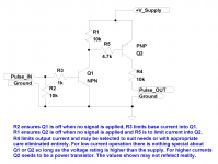
At lower frequencies an conventional audio amplifier will likely show the effects of not being direct coupled on your unipolar signal. Audio gear is designed for inputs and outputs to swing +/- of the ground (read 0v) reference. At the frequencies you need you could likely drive the gate of an enhancement mode MOSFET directly, or even a BJT's base via resistor and have that device switch the output of almost whatever voltage source you like with minimal circuitry. I'd think little more than an appropriate MOSFET and a gate pull-down resistor or a BJT with pull-down and base current limiting resistors and a suitable power source. I'll assume the resistance you are driving is large and required current will be small.
At lower frequencies an conventional audio amplifier will likely show the effects of not being direct coupled on your unipolar signal. Audio gear is designed for inputs and outputs to swing +/- of the ground (read 0v) reference. At the frequencies you need you could likely drive the gate of an enhancement mode MOSFET directly, or even a BJT's base via resistor and have that device switch the output of almost whatever voltage source you like with minimal circuitry. I'd think little more than an appropriate MOSFET and a gate pull-down resistor or a BJT with pull-down and base current limiting resistors and a suitable power source. I'll assume the resistance you are driving is large and required current will be small.
Thanks, we see much better what you need.
I think all you need is a solid state relay and a power supply.
Solid state relay - Wikipedia, the free encyclopedia
A fixed voltage power supply or variable voltage if needed.
I think all you need is a solid state relay and a power supply.
Solid state relay - Wikipedia, the free encyclopedia
A fixed voltage power supply or variable voltage if needed.
still a audio power amp could be a cheap solution with some modification for DC coupling - nice to have the schematic and someone with soldering skills
as long as this is for artifical muscle research - hooking human subjects to amplifiers with conductive gel electrodes requires considerably higher electrical safety standards than audio amps are designed for
as long as this is for artifical muscle research - hooking human subjects to amplifiers with conductive gel electrodes requires considerably higher electrical safety standards than audio amps are designed for
Last edited:
Hi guys,
Thanks again for all your help, it's great!
jkuetemann - thanks for your explanations, I'm trying to learn but it seems there's so much! I've had a quick look at the MOSFET idea - would I be looking at a n-channel or p-channel one? Does it matter if I wanted to generate a bipolar pulse instead of a unipolar one?
I know that this exact system has been set-up before using a MOSFET DC-DC power amp designed for audio so it should be possible, but finding a not-too-expensive suitable amp that can do the job is not that easy! The one I have seen used for this before is a Rolls Ra1000b but this model does not work on UK power supply, plus I can't find any as they no longer make them. So maybe making one would work...
If the smallest pulse width I'd be using is 0.2ms that would give a frequency of 5000Hz is that right? (If the frequency is the inverse of the cycle length from leading edge of one to leading edge of the next pulse?) And 4ms pulses would give a frequency of 125 Hz? So if I need an amp with a bandwidth of 10x this frequency then that would be 50,000Hz assuming a 0.2ms pulse width? Is that correct or have I gone wrong?
OK so I would need:
1) a power supply +/- 80V
2) a bandwidth of 50,000Hz
3) DC-DC coupling (?)
What else do I need to consider? What about distortion of the signal or signal-to-noise ratios and so on or is this not a factor in this kind of system?
Thanks again for your help and jcx don't worry, this is definitely not for use in humans! 🙂 Oh and by the way I'm a she not a he...😛
Interesting problem...
One problem I forsee is that using a high speed switch (which seems the obvious choice) has the real drawback that the amplitude of the output can not be controlled just by varying the input amplitude. It could be done easily by varying the supply to the switch, that is the 0 to 80 volts and keeping the input constant at 5 volts. The rise and fall times could be very fast with quite a simple circuit.
To have the output respond linearly to the input requires a "proper" amplifier, the downside of which is that it would be more complex.
The bipolar or AC output is another issue if all you have is a 0 to 5 volt USB generated signal. That would require the output of the "amplifier" to be AC coupled such that a 50/50 mark space sat equally above and below ground with DC coupling for allowing say a 50/50 output at 0 to 70 volts or if needed 0 to -70 volts.
- Status
- Not open for further replies.
- Home
- Amplifiers
- Solid State
- amplifying a square waveform? I'm a newbie - please help!