the OP mentins a USB DAQ - some have DAC Vout, often even bipolar
the droop is likely due to the audio signal AC coupling
making modifications for DC coupled operation is easier with the schematics, likely there is an input coupling C and possibly a feedback DC blocking C that would need to be shorted
but you need to look at the whole amp circuit to see if bias conditions allow or if offsets would be too big, possibly protection circuits would also have to be disabled
some higher quality USB DAQ are galvavically isolated so bridging 2 amp channels to double Vswing could be easy - though not that hard for a electronics hacker even without the isolation
Hi,
Thanks again for all the replies, it seems that maybe a DC-DC amplification would maybe help solve the problem here?
Bearing in mind my inexperience in this area, can anyone suggest a start point for building a MOSFET amplifier myself ( I can probably get some help but I'm not sure where to even begin with suitable schematics etc.)? What characteristics would I need to be looking for when getting hold of components fo this type of amp?
Alternatively, can anyone suggest a model of amp that I could try to purchase that could do the job? I've done a search for Dc-DC amps and found a few old Technics models but I can't seem to find any specifications for them. I know other people have used older audio amps for this before but I don't know if there are any specific models that I could look for?
Thanks again, I am in awe of the extent of electronics knowledge from people here, brilliant!
Do have a budget to work to with this ?
Also its important for you to be absolutely sure on the specifiations you need and what is and is not acceptable. This is important because it makes a huge difference to the design.
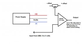
When you talk of a signal of say 0 to 70 volts then that implies an amplifer (speaking of an audio amplifier) that would be capable of 0 to -70 as well... and that's a big (in audio terms) amplifier. In other words it would swing 140 volts peak to peak centered around zero. That also presents a very real shock hazard even at a low current of say 50 millamps max output.
You don't need the ability to work into a low resistance load (like an audio amplifier does) and so you really need a purpose designed high voltage but low power amplifier which could be fairly easily built... but it's still very important to know the exact requirements.
This is a simple block diagram but the main question to me is the "bipolar" as you call it output capability as that needs an amplifier running on a dual ( a plus and minus) supply so that the output can swing above and below zero.
Also how would you implement that ? Does the output of your USB DAC allow you to set an output that would correspond to exactly what you want in terms of the bipolar output and the relative levels above and below zero for the output waveform. If not then the amplifier would need some form of manual offset for you to alter the position of the output waveform relative to zero and you would need some means of measuring that in use such as an oscilloscope.
Hope that makes sense.
Also its important for you to be absolutely sure on the specifiations you need and what is and is not acceptable. This is important because it makes a huge difference to the design.
When you talk of a signal of say 0 to 70 volts then that implies an amplifer (speaking of an audio amplifier) that would be capable of 0 to -70 as well... and that's a big (in audio terms) amplifier. In other words it would swing 140 volts peak to peak centered around zero. That also presents a very real shock hazard even at a low current of say 50 millamps max output.
You don't need the ability to work into a low resistance load (like an audio amplifier does) and so you really need a purpose designed high voltage but low power amplifier which could be fairly easily built... but it's still very important to know the exact requirements.
This is a simple block diagram but the main question to me is the "bipolar" as you call it output capability as that needs an amplifier running on a dual ( a plus and minus) supply so that the output can swing above and below zero.
Also how would you implement that ? Does the output of your USB DAC allow you to set an output that would correspond to exactly what you want in terms of the bipolar output and the relative levels above and below zero for the output waveform. If not then the amplifier would need some form of manual offset for you to alter the position of the output waveform relative to zero and you would need some means of measuring that in use such as an oscilloscope.
Hope that makes sense.
Attachments
Why not just use a low voltage switch with one MOSFET and a transformer to step up the voltage. On the output of the transformer use a multi-turn 10K pot to adjust the voltage applied to the patient. That is how most TEMS machines operate.
The most complex part is writing a few lines of code to generate whatever stimulus you want to apply.
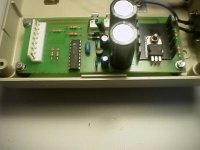
Nothing new about these things, this one is called Transeva and we made it around 1997 or there about.
The most complex part is writing a few lines of code to generate whatever stimulus you want to apply.
Nothing new about these things, this one is called Transeva and we made it around 1997 or there about.
Attachments
- Status
- Not open for further replies.