Yes, it has nothing to do with stability stability, that’s why it has to be removed as a confounder during initial testing with a resistive load.
10 kHz 28Vpp response into 150 nF+10Ω || 8Ω
No signs of any instability and we could now identify if there was any oscillation from amplifier.
That’s good. But what is it at 3V pk-pk into just a resistive load and then at 80% of full output swing - again resistive load? (you may have to disconnect your Zobel for the high power test)
Another approach is not to have too many blocks around which feedback is applied.In order to spot such issues, take apart the amplifier into smaller chunks like the LTP, currrent sources, current mirrors, gain stages, buffers and so on and investigate each on their own, both in AC and transient response. You may be surprised how weird some circuit blocks can behave. Once each block is optimized, put them together again and see whether they (still) play together nicely.
The Kenwood amp that PMA cloned has the most compensation capacitors that I have ever seen (7). This is a sign that stability may be precarious.
Ed

But what is it at 3V pk-pk into just a resistive load and then at 80% of full output swing - again resistive load?
3 Vpp
Amplifier is clipping at +/- 16 V so 80% is 25 Vpp.
I see the resistive load - I missed it in my earlier post. Apologies.Yes, as said, it was adjusted at the signal generator. Not caused by amplifier.
Here are unlimited responses at 100 kHz. Amplifier has +/- 17 V supply.
4 Vpp/8Ω
View attachment 1253127
28 Vpp/8Ω
View attachment 1253128
The rise time <> bandwidth rule of thumb indicates a closed loop bandwidth of 1.16 MHz. Do you think that’s a good idea?
Depending on my goals, nothing wrong with that.
Actual closed loop bandwidth is 1.3 MHz. During development, amplifier was operating as perfectly stable with any capacitive load at 1.8 – 2 Mhz. All above tests are without input RC filter, which this amplifier has.
My goal was to see how far I can get with low power class A amplifier at all parameters: distortion, slew rate, output impedance, noise, EMI immunity, consistent harmonics profile through all power levels and loads, while not compromising stability at all.
PCB is 4-layer with outer layers used as static shields, so amplifier is safe even from some high EMI pulse affecting stability. Needles to say, this design was thoroughly tested (harassed actually in all imaginable ways) for half a year and it passed.
Not only the global loop stability is important. When using 3EF and especially when the supply voltage is higher than, say, +-40V, the triple must also be stabilized. (In my experience, the simulator does not help much in revealing the triple instability against the capacitive load)
Triple emitter followers are difficult to stabilize. Put a borderline stable triple inside any feedback loop and go crazy with loop compensation to no avail.
Simulation has helped me a lot improving stability of a triple, but derived component values may just be a guesstimate to start with.
Simulation has helped me a lot improving stability of a triple, but derived component values may just be a guesstimate to start with.
I suspect the problem with EF3 is that an emitter follower can draw unexpectedly large currents from its base if the emitter gets yanked by the next stage or load. Multiply by three. A small series resistor on the base prevents backward propagation.
Ed
Ed
I agree that 3EF is tricky. Even if there are base stopper resistors, as in case of the tested amplifier
https://www.diyaudio.com/community/attachments/ka5010clone_sch-png.1053399/
https://www.diyaudio.com/community/attachments/ka5010clone_sch-png.1053399/
I found c. 10 ohms in the base of the drivers with 470 pF to the rails + 15 ohms with 4.7 to 10 uF from the driver collectors to ground cured all problems. You have to use base stoppers in the OP devices as well - I use 4.7 ohms but I’ve seen 2.2 to 10 Ohms. A Zobel network is mandatory IMV as well (10 ohms + 0.1 uF) from the output rail to ground. I’ve built about 20 big 240W amps using this without issue.
On one of my very early EF3 designs (‘Ovation 250’) from 2006, I got an interesting article off the web about emitter follower instability - PSpice application note IIRC. Bob Cordell covered this in a more practical way in his book a few yrs later.
In the original nx-Amp I put the Zobel off board on the PSU which was not ideal. The Zobel loop area must really be as small as practicable and located on the main PCB near the OPS just before the output L.
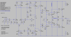
I wouldn't use C3/C4, they degrade the phase margin of the global loop. R6+C5, R8+C6 and base stoppers are sufficient for stability. In addition, the VAS should be loaded with zobel 22-100p + 10-33R.

Last edited:
Capacitors C3 and C4 may have a small resistor in series (~10R). This forms a snubber taming the high Q base to collector capacitance of Q7 and Q8.
While I‘ve seen capacitors C1 and C2 in schematics quite often, I don’t understand their purpose. Aren’t they defeating R4 and R5?
A neat trick is to increase R1 and R2 to 10-15 Ohm and put ferrites (max. ~1uH) in parallel. This greatly improves AC stability without messing up DC stability. Note that base stoppers should be maximum ten times the emitter resistors value. The ferrites in parallel circumvent this.
The pole of a 22 Ohm resistor and 470pF capacitor from the driver base to its collector is at >15 MHz. If that is causing loop stability problems, there are other severe loop compensation issues. This technique BTW was what was discussed in the app note I mentioned earlier and covered in Bob Cordell's book - see pages 205 to 209 (2011 edition).
In the case of C1 and C2 above, I suspect it is an attempt to introduce an HF zero to counteract the HF pole in the OPS. Unless the zero frequency is carefully chosen, it will lead to severe gain peaking and rapid phase accumulation when combined with the OPS HF pole. If there is not enough gain margin, HF instability will result.
Although modern sustained beta bipolar transistors allow one to close the main feedback loop at higher frequencies, the high fT's (30 MHz), mean they can more be more susceptible to HF parasitic oscillation. In the Ovation 250 I mentioned earlier, the output devices were MJ21193/4 with an fT of 4 MHz and Cob of 500pF, whereas the MJE1302/1381 have an fT of 30 MHz - i.e. nearly 10x. Before applying the OPS parasitic damping, the Ovation 250 amplifier oscillated at >1 MHz.
Using modern sustained beta devices with fT's of 30 MHz, it is best to err on the side of caution and close the main feedback loop at not more than 1-1.5 MHz. This still leaves you with plenty of loop gain at the top of the audio band and enough gain margin to apply the damping techniques outlined in Cordell's book.
IMHO, C3(C4) is a bad practise. I used to use it a lot in the past, now I'm trying to eliminate it. C1,2 can increase the gain margin.
if you don't already know, something to read
https://nathaliebeimler.com/tech/audio_amplifier_output_stage_comparison.html
if you don't already know, something to read
https://nathaliebeimler.com/tech/audio_amplifier_output_stage_comparison.html
That analysis is not representative in the context of what we are discussing here - it is a diamond structure. And the input damper is simply also limiting the bandwidth. Please read the Cordell I referenced and his discussion on the subject. As I mentioned earlier, if the damping network R4, R5 and C3, C4 are causing loop instability problems because are additional phase shifts with the values shown, you have problems elsewhere. If you close the main feedback loop on a triple at the recommended 1-1.5 MHz, you will not be creating enough phase shift at 15.6MHz for it to be an issue provided you have the gain and phase margin available at the ULGF - in a well compensated system this means >45 degrees (preferably 60) and >10 dB gain margin. The OPS in almost any audio amplifier sets the upper limit on ULGF and that is a hard rule that cannot be challenged.
I stand by what I wrote. The right way is not to use C3,C4 and apply C1,C2. Try to simulate.
Of course, do not forget add R6+C5, R8+C6 to the real amp.
Of course, do not forget add R6+C5, R8+C6 to the real amp.
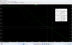
My simulation of the blameless with tmc compensation. The ULGF is about 1MHz.
The differences are greater when higher ULGF is used.
The differences are greater when higher ULGF is used.
Attachments


Last edited:
I still don't really get your point. I put data derived from your plots into a table for my convenience and easier comparison:
It is obvious that the caps to the rails do have some impact on the speed of the OPS, but I don't really understand how this affects loop compensation that much.
Local instability of the OPS may be just swamped by simulating a whole amplifier with the OPS in the loop.
Have you investigated the OPS on its own and the effect of different options to tame the beast?
Adding some real world wiring inductance (at least a guesstimate of it) to the simulation makes a big difference, too, especially in OPS.
| no caps | caps to rail | caps parallel to base stoppers | |
| UGLF | 980kHz | 970kHz | 970kHz |
| Phase margin | 63° | 59° | 63° |
| Gain margin | 9dB (4.4MHz) | 9dB (3.6MHz) | 10dB (4.4MHz) |
| Group delay | 8ns | 21ns | 8ns |
| Delta | 3.4MHz 9dB 82ns | 2.7MHz 9dB 67ns | 3.4MHz 10dB 69ns |
It is obvious that the caps to the rails do have some impact on the speed of the OPS, but I don't really understand how this affects loop compensation that much.
Local instability of the OPS may be just swamped by simulating a whole amplifier with the OPS in the loop.
Have you investigated the OPS on its own and the effect of different options to tame the beast?
Adding some real world wiring inductance (at least a guesstimate of it) to the simulation makes a big difference, too, especially in OPS.
What don't you understand ? Data says everything.
I have also verified it on my real amplifier.
Another example
blameless topology, 3 pole TMC, 3EF
driver tr 2SC4793/2SA1837, base stoppers 47R
no cap across base stoppers, no BtoC cap on drivers
ULGF 3.2 MHz
PM 64 deg
GM 8 dB
no cap across base stoppers, 220pF BtoC cap on drivers
ULGF 3.1 MHz
PM 44 deg
GM 9 dB
470pF cap across base stoppers, no BtoC cap on drivers
ULGF 3.1 MHz
PM 64 deg
GM 17 dB
470pF cap across base stoppers, 220pF BtoC cap on drivers
ULGF 2.9 MHz
PM 50 deg
GM 17 dB
The 220pF caps on the drivers degrade the PM by about 20 degrees (LTSpice says, not me)
I have nothing to prove anymore, try it.
Last edited:
- Home
- Design & Build
- Electronic Design
- Amplifiers - Feedback/Loopgain stability simulated vs. real world