My first attempt at building a Amp from scratch.
Intention is to learn as I try and try again.
Intention is to learn as I try and try again.
Attachments
Last edited:
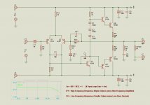
For lower noise, I would drop RF1 to 22K, and RF2 to 1K. Also add a 1K in series with the Q1 base, with a cap to set the high frequency cutoff.
For lower noise, I would drop RF1 to 22K, and RF2 to 1K.
Good advice, but will mean you need to increase CF2 to 100uF.
1000uF is pretty low for smoothing caps. Probably OK for the lower of your voltage target and with 8 ohm load only.
And why no bias ? Unless its only for low frequency use, you want some bias to get rid of crossover distortion.
Its only another transistor, 2 resistors and a pot, and these parts replaces the three diodes.
Its only another transistor, 2 resistors and a pot, and these parts replaces the three diodes.
the input differential pair should be fed from a constant current source or a least be stabelised with a zener diode and resistor conbination R4 should be replaced with a constant current source or bootstrapped
base to emitter resistors typical 100 ohm should be placed on output devices
regards trev
base to emitter resistors typical 100 ohm should be placed on output devices
regards trev
Last edited:
For lower noise, I would drop RF1 to 22K, and RF2 to 1K. Also add a 1K in series with the Q1 base, with a cap to set the high frequency cutoff.
Thanks for your advice, i was thinking they are to high, i should have just lowered them, ill make changes.
1000uF is pretty low for smoothing caps. Probably OK for the lower of your voltage target and with 8 ohm load only.
The amp is intended for two types of builder, the person who is new to
diy audio project building but wants a amp with decent sound,
That builder would build a seperate PSU with 6800uF caps. Still Keeping
the 1000uf on amp board.
The Second type of builder is the complete novice, early teenager with
very little diy and electronics experience, then all that needs to be
added to amp board is transformer and bridge using onboard caps, ofc
amp will then have limited output, but be easier to build.
And why no bias ? Unless its only for low frequency use, you want some bias to get rid of crossover distortion.
Its only another transistor, 2 resistors and a pot, and these parts replaces the three diodes.
I wanted it to be a build and work circuit, no setup needed,
So a builder can make it and it works without needing a Meter
or knowledge or measuring bias currents etc.
the input differential pair should be fed from a constant current source or a least be stabelised with a zener diode and resistor conbination R4 should be replaced with a constant current source or bootstrapped
I tried to leave out as many transistors as i could to make building and
understanding of the circuit as simple as posible.
So i left out Constant Current transistors in Diff Pair and left out Current
Mirror in VAS stage.
I was hoping that a modest output could still be reached, knowing ofc that
clipping would occur earlier that if the diff pair was balanced and output bias was set by servo and constant current.
But if its the general opinion that leaving these features out, will degrade quality and power to greatly, then ill revise circuit.
Otherwise ill add a zener as you adviced.
http://i.imgur.com/tHz01.png <-- i would atleast add the bootstrap circuit.
And you still need a meter as you need to manually set the DC offset with a circuit like this. Yes a meter is mandatory, and so is a scope, if you don't have either of these, there is no way to make this circuit work.
And you still need a meter as you need to manually set the DC offset with a circuit like this. Yes a meter is mandatory, and so is a scope, if you don't have either of these, there is no way to make this circuit work.
Thanks for reply.
Ive not had time yet to make trial PCB, but have breadboarded it.
Ofc its not ideal on breadboard but it seems to work well from schematic from Post 1,
with lowering of feedback values.
Ill be making a PCB tomorrow and try it out, test square wave response and
Gain bandwidth.
There was a greater offset on V+ to npn than there was to V- to pnp,
ill be adding a 2.2k pot in series with R3 and adjust R3 a bit lower.
Just a Question, what size zener is usually used to stabilize Diff pair.
12V ? or can I USE 15v, Does it make a difference, i cant really see that it should.
What current should I aim for in Diff pair, since my Vsup can be from 18-35V.
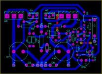
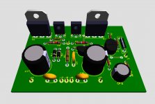
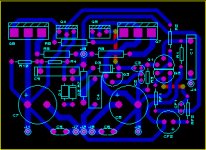
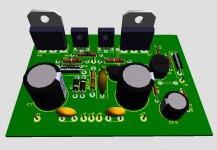
Here is updated PCB's.
12V ? or can I USE 15v, Does it make a difference, i cant really see that it should.
What current should I aim for in Diff pair, since my Vsup can be from 18-35V.
Here is updated PCB's.
Attachments
well ...
starting from phrase one in your post
"""Im new to Amplifier Design and very new to Audio PCB Layout.""" i will have to say that you are new to amplifiers anyway ...just skip the design and the pcb .... there is a hell of a lot more to learn before you start designing your own pcb .... design your own amplifier will take way too much time than you expect ....
now i can see that you can use a simulator then very well i will have o think that you are probably young and experienced with computers ...so here is lesson #1
there is a million of things that simulators cannot tell you about amplifiers and the problem is that some of them are critical
your circuit has a number of problems your pcb has a bigger number of problems ....
now if you want some advice from someone that already been in your position ( young and inexperienced )
--- run simulations just to get an idea but actually built any amplifier from the forum or kit from ebay
---understand how it works...
---read books that describe the circuit , topology, pros and cons principal of operation
--- ( internet might become handy there but also any thread regarding DX amplifier for example has loads of information that you can use ) ...
---tweak it to see difference and how far you can go
and then start design things on your own ....Expected to be a time consuming thing to do
now .... starting like that posting a circuit that is a bad simulation result and a PCB that is horrible will end up to the nice kind and polite people of the forum will see and try to help you out , debug your circuit and correct your PCB but trust me this is going to happen in a language that you will not understand since you don't have the experience and every advice you get will arise another 10 questions and another 10 alternatives ...
A simple amp like this should be breadboarded first. There will be things like decoupling and compensation to be aware of. Layout is very important. You are much less likely to wast a PCB if you can work the bugs out of it with a temperary layout first on breadboard. Using a simple bias servo for the outputs is not much complexity to add, and you would adjust the bias pot only once.
I have built my fair share of amplifiers and circuits.
My field tho is embedded control, and so yes i use a computer to program and prototype on software.
Nothing wrong with simulations, the point of this thread is not to discuss the
validity of simulation.
As stated in a Previous post, this circuit has been breadboarded and is working as
it is supposed to.
The question here is not if it works, it does,
The advice asked is to improve it and make it a bit better.
Making comments like to learn topology etc is unfounded, ive fixed my share of
consumer products tho, as i said previously, i design control and monitoring systems.
Ive tried to compensate for things like decoupling high frequency noise.
I thank all those for contructive comments
None of the persons you see in the forum is born with the amplifier knowledge most of them work very hard to come this far .
Instead of bragging about your circuit it will be better to keep a lower profile and try to read and learn before you say things like that ...
there is a big difference from what you say ""working"" amplifier than an amplifier that simply some sound comes out of it
example :
your simulator thinks that the source is perfect in real life in most of sources and most working environment there is loads of RFI and EMI
your input needs filtering
Run this circuit to anything above 20+20 volt for a period of time at rated power and will shelf destroyed from thermal runaway your simulator cannot calculate that when the temperature increase the bias of the amplifier will also increase since there is no thermal compensation .... If the amplifier plays for a period of time at rated power will simply blow ( unless huge heatsink )
Your simulator cannot tell you anything about your PCB design ....excuse my sayings but with such a horrible pcb expect all the simulation results to be seriously altered for the worst and even drive your amp to oscillation
these are the problems one can see with naked eye expect around 10-20 serious mistakes in pcb and circuit that will make the difference from a """"playing """ amplifier to a ....working amplifier
Finally i will excuse my shelf from your thread and remind you once more that all the info you need regarding circuit topology filtering and stability issues together with a load of pcb design tips exist in the forum and the only thing you need to do is some reading ...
happy regards
sakis
I don't think that deleting the thread is in anyones interest. Sakis has stated his oppinion, which could in my oppinion have been done a little less harshly.
But I think he feels that by being blunt, that he can save you some time and frustration. I can't really comment as I have pretty much zero knowledge about amplifier design.
Sakis has said he will leave the thread now. Vostro I suggest that you put it aside (or perhaps revisit it later) and continue on with your project. We all have different ways of learning, and for some of us jumping in and doing, making mistakes and learning from them is the best way.
Tony.
 diyAudio does not delete threads simply because of disagreements in them. (Few threads would survive). If you are not happy with a thread, leaving it is the best advice.
Abuse should be reported using the "Report Thread" button. (in the lower left of each post).
OT remarks removed.
lol I'm back for more punishment.
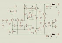
Well heres latest schematic.
Im learning more, please keep constructive comments comming,
not comments like - go read a book or go do gardening cause you suck at electronics.
lol 🙂
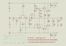
Well heres latest schematic.
- Supply Voltage Increased to max 50V.
- Rf1 increased to allow greater output with 1V signal input.
- Cf1 removed, value needed to be decreased to much cause of bigger Rf1.
- Signal ground isolated.
- C7-8 Increased to 6800uF 63v, I have a tray of about 20, so might as well use em.
- Transistors changed to accomodate Higher supply.
- 2 Output pairs to stabilise at higher output power, (using 6R speakers)
- Added Transisor instead of 3 diodes, RV2 to set offset, 100mA per rail.
- Rv2 instead if R3 to set DC offset at output.
- 15V zener added to pass about 1mA per Q1 and Q2.
- Tossed in some 100pf to make sure its a amplifier and not a oscillator 😛
Im learning more, please keep constructive comments comming,
not comments like - go read a book or go do gardening cause you suck at electronics.
lol 🙂
Attachments
Last edited:
- Status
- Not open for further replies.
- Home
- Amplifiers
- Solid State
- Amplifier Trial Design with 18V to 35V Supply