D
Deleted member 148505
Product updates:
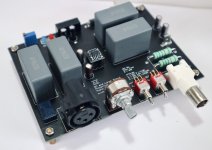
New JLE Interface partial board: Soundcard "manual ranger" with pre-soldered INA1651, ultralow-noise supply (TPS7A4901 / TPS7A3001), and all SMT parts, up to 90Vrms floating input, balanced output, and isolated usb power.
JLE Interface is now available! I will post measurements once I receive my DAC and E1DA Cosmos ADC. (Still searching for a cheap, decent DAC with volume knob)
I'm expecting around -106dB THD+N performance.
(20Hz to 20kHz at 4Vrms balanced output)
Attachments

D
Deleted member 148505
For C17, get 25V or higher. You can also use 100nF for the meantime (same as EVM) if you want to make it work right away
For poly caps, get 100VAC or higher.
You also need 10K ohms 0603 for changing the osc freq.
Regards,
Lester
1uF was my default cap for VBG (same as datasheet). I've tried 100nF 0603 (same as EVM) and I think this provides better sound. You can use 100nF for C17
For Sylph-D200 this is C19.
D
Deleted member 148505
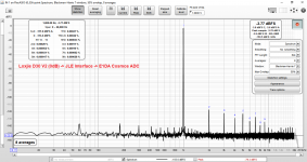
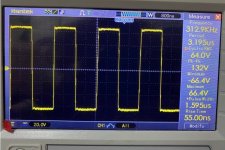
JLE Interface initial measurements
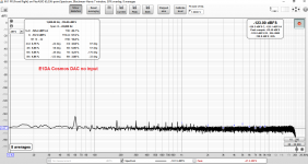
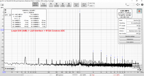
Quick measurement of JLE interface, it has 10dB noise floor penalty when inserted on the ADC. THD is 110dB, THD+N 106dB. I believe it can get better results when a good signal generator is used.
Quick measurement of JLE interface, it has 10dB noise floor penalty when inserted on the ADC. THD is 110dB, THD+N 106dB. I believe it can get better results when a good signal generator is used.
Attachments

D
Deleted member 148505
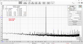
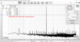
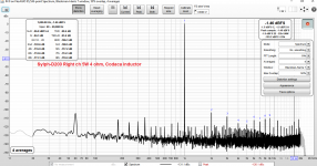
Sylph-D400 Mono Performance
Measurement at 4ohm 5W and 10W. Most probably the FFT spectrum at 5W 4ohm will be almost the same when measured in ASR. Also, I don't use special dummy load, just the green 1000W wirewound type.
5W 4ohm = 94dB SINAD
10W 4ohm = 97dB SINAD
Measurement at 4ohm 5W and 10W. Most probably the FFT spectrum at 5W 4ohm will be almost the same when measured in ASR. Also, I don't use special dummy load, just the green 1000W wirewound type.
5W 4ohm = 94dB SINAD
10W 4ohm = 97dB SINAD
Attachments
What is the corner frequency on the DC protection cap (filter)?
It is always good to keep in mind that a series capacitor only blocks steady-state DC. When a fault condition occurs, or when the device first sees DC after a no DC condition, you have a transient event like a step input. In that case, the step up in DC will cause a spike in the output of the filter that may be significant. The spike peaks at some value and then quickly falls back to zero as the steady state DC condition and charge across the cap has been achieved. The peak voltage of the transient spike should not exceed the breakdown voltage of any downstream component, and this is what determines the actual level of DC protection that the capacitor provides.
Have you checked that, JLesterP?
D
Deleted member 148505
What is the corner frequency on the DC protection cap (filter)?
It is always good to keep in mind that a series capacitor only blocks steady-state DC. When a fault condition occurs, or when the device first sees DC after a no DC condition, you have a transient event like a step input. In that case, the step up in DC will cause a spike in the output of the filter that may be significant. The spike peaks at some value and then quickly falls back to zero as the steady state DC condition and charge across the cap has been achieved. The peak voltage of the transient spike should not exceed the breakdown voltage of any downstream component, and this is what determines the actual level of DC protection that the capacitor provides.
Have you checked that, JLesterP?
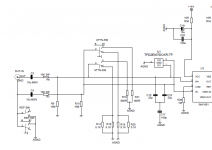
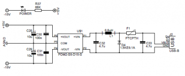
Hi Charles,
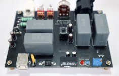
Input corner frequency is 15.92 Hz.
TPD2E007 will take care of transient spikes.
Attached audio input and usb power section of the interface.
Regards,
Lester
Attachments
D
Deleted member 148505
Hi Charles,
Input corner frequency is 15.92 Hz.
TPD2E007 will take care of transient spikes.
Attached audio input and usb power section of the interface.
Regards,
Lester
If I am reading the datasheet correctly the TPD2E007 does not conduct from pin 1 or 2 to ground until a 14V differential has built up. That is about 25dBu or 23dBV. This may exceed the limits for some audio interfaces.
I am thinking about the case where the user is testing an amplifier and the output fails to one or the other rail voltages, e.g. a few tens of volts DC. Or somehow the user connects to a circuit that has a mic bias applied to it (up to 48Vdc). The step in DC will make it past the input caps briefly as an AC "spike" that is 50% or more in amplitude of the DC level. So it falls to the TPD2E007 to shunt this to ground, and until it reaches 14 Volts nothing will happen. You should be able to sim that behavior.
It might be good to let the buyer know what the minimum level of transient might be, e.g. 14V, so they can see if this would exceed the max input voltage for their interface.
Otherwise I think this in an interesting product. Thanks for sharing the schematic so I can see the signal path and protection.
D
Deleted member 148505
If I am reading the datasheet correctly the TPD2E007 does not conduct from pin 1 or 2 to ground until a 14V differential has built up. That is about 25dBu or 23dBV. This may exceed the limits for some audio interfaces.
I am thinking about the case where the user is testing an amplifier and the output fails to one or the other rail voltages, e.g. a few tens of volts DC. Or somehow the user connects to a circuit that has a mic bias applied to it (up to 48Vdc). The step in DC will make it past the input caps briefly as an AC "spike" that is 50% or more in amplitude of the DC level. So it falls to the TPD2E007 to shunt this to ground, and until it reaches 14 Volts nothing will happen. You should be able to sim that behavior.
It might be good to let the buyer know what the minimum level of transient might be, e.g. 14V, so they can see if this would exceed the max input voltage for their interface.
Otherwise I think this in an interesting product. Thanks for sharing the schematic so I can see the signal path and protection.
I haven't sim'ed it yet, but yes the 14V transient will be translated into JLE's output. If the interface or ADC is powered on, I think most can handle a 14V transient in their inputs?.
Also the reason why I didn't remove the protection diodes in my E1DA ADC, there might be a perfect transient waiting for it.
Regards,
Lester
Last edited by a moderator:
D
Deleted member 148505
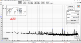
TPA3251 amp module
I'm developing a TPA3251 amp based on Sylph-D200.
5W 4 ohm performance will be around -91dB to -92dB THD+N since it will use cheaper voltage regulators. PCB length will be reduced from 150mm to 137mm.
Inductors will be Codaca 1D17A equivalent and with only 2 bulk caps.
Actually I'm noticing a better bass response with smaller bulk caps (1500uF * 2)
Attached THD measurements
Attachments
D
Deleted member 148505
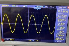
Tectonic D500 with IPP320N20N3 mosfets at +/-64V rails.
Switching node and carrier residual. Very clean 🙂
I have 3 pairs left and next stock of IPP320N20N3 will be on Jan/Feb 2022
IRFB4615/5615 will be used on +/-45 to +/-65V rails
Switching node and carrier residual. Very clean 🙂
I have 3 pairs left and next stock of IPP320N20N3 will be on Jan/Feb 2022
IRFB4615/5615 will be used on +/-45 to +/-65V rails
Attachments
It's been a long while but this afternoon I picked up my TICore260BTL build again. I need to install the hi-gain daughterboard that I bought back along using Lester's instructions in post #1282.
I've done the easy bit - removed the input caps and installed wire links. Tomorrow I'll swap in the Silmics and start on the smd part changes
As it's been a long time I may need to check in to make sure I don't get it wrong.
I've done the easy bit - removed the input caps and installed wire links. Tomorrow I'll swap in the Silmics and start on the smd part changes
As it's been a long time I may need to check in to make sure I don't get it wrong.
D
Deleted member 148505
Nice, for the input coupling caps going to TPA chip, you can leave the Silmics as they are. They are very good sounding (granted that they are the only silmics in the signal path).
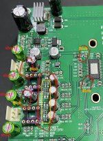
These are the important mods for TICore260BTL
You need to disable PFFB and make the module sing first. After all the mods, and the module still works perfectly fine then you can replace the PFFB values (PFFB with 7dB NFB just like in my Sylph-D200). PFFB implementation in TICore260BTL is the same as SLAA788A TPA3255 which only has 5.57 negative feedback.
Regards,
Lester
These are the important mods for TICore260BTL
- For C17, VBG cap you need to replace it with 0603/0805 100nF SMT cap.
- Remove / desolder C5, C6, C7, C8
- Blobs in the attached pic
You need to disable PFFB and make the module sing first. After all the mods, and the module still works perfectly fine then you can replace the PFFB values (PFFB with 7dB NFB just like in my Sylph-D200). PFFB implementation in TICore260BTL is the same as SLAA788A TPA3255 which only has 5.57 negative feedback.
Regards,
Lester
Attachments
This is getting really complicated Lester - so I would need to do the mods in post #1282 and the extra ones you list above?
How do I change the oscilating frequency and what benefits is doing so?
Why do I need to disable PFFB?
It's a bit of a worry when you say "After all the mods, and the module still works perfectly fine..." - is there something, apart from my own abilities to execute the changes, that makes a problem likely?
D
Deleted member 148505
Yes, post 1373 are just mods for sound improvement. I think I have repeated the solder blobs / bridges instructions.This is getting really complicated Lester - so I would need to do the mods in post #1282 and the extra ones you list above?
If you change the osc freq and output cap, the pffb values on your board will not work so you need to disable it. Also I think non-PFFB sounds better. Changing the osc freq and output cap is required for the new PFFB valuesHow do I change the oscilating frequency and what benefits is doing so?
Why do I need to disable PFFB?
It's a bit of a worry when you say "After all the mods, and the module still works perfectly fine..." - is there something, apart from my own abilities to execute the changes, that makes a problem likely?
Hmm, I'm not doubting your ability. I think you just need to check if the amp is working every set of mod that you apply just to lessen the probability of mistake.
Regards,
Lester
Thanks Lester. So yes, the sensible thing is to take it a step at a time.
I'll start with the changes detailed in post 1282 and see how that goes.
I assume the amp should function with those changes implemented and without touching the oscillating frequency, output cap, PFFB?
I'll start with the changes detailed in post 1282 and see how that goes.
I assume the amp should function with those changes implemented and without touching the oscillating frequency, output cap, PFFB?
Ray, I just did the 'simple ' mods. Didn't play with the frequency or pffb on the TiCore. A fine sounding amp nonetheless.
I have a different daughterboard configuration Jim, for additional gain, hence the additional changes in #1282.Ray, I just did the 'simple ' mods. Didn't play with the frequency or pffb on the TiCore. A fine sounding amp nonetheless.
Post #1282 surgery performed! Now I just have to solder in the Silmics and check for lifesigns.

- Status
- Not open for further replies.
- Home
- Vendor's Bazaar
- Amplifier Modules and PCBs For Sale