Hello everyone!
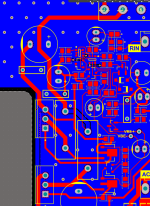
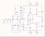
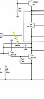
I decided to design a 30W RMS 2 channel amplifier using smd components for the input,the vas, the driver stage and the mje15028/29 bjts for the class ab output stage. For the input stage transistors i have used the dual bjt in package transistors BC847/57BS, the bc847/57 for the vas, and the BCX53/56 transistors for the driver stage. I have set the gain to 27db and the miller cap to 120p. Tail current is set to around 2mA and the vas current to around 6mA. I have set the vbe multiplier to around 1V at the point before output transistors start conducting. Pi filters at the rails, the resistors are shorted because i didnt have the component on hand but no big deal.
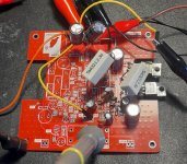
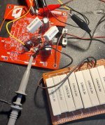
I have soldered all the component by hand, and i have measured the current source resistors and they seem to be within spec. I also have soldered 2 boards to see if i have made a soldering mistake but the same issue.
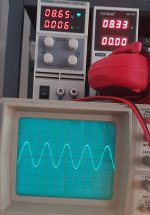
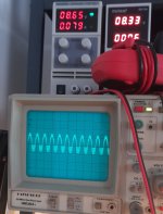
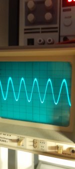
The issue that i have is that when the output is not loaded the amplifier is outputting a nice and clean signal and within spec. Once i add a resistive load at the output , even a 100omhs resistors the amp loses stability and starts oscilating.
I also noticed that when signal is 0 and i have a load connected i have a stable few milivolts noise each second. Noted!
What i have tested:
1) tried to slightly increase the miller cap. no noticeable difference.
2) i have disoldered the output bjts and drive the output with the drivers as i can do that and see if it is mje issue. no difference.
3) applied load directly at output resistors to see if its feedback or an output trace inductance issue. no difference
4) i have added 100p caps by hand between output and various nodes. no difference.
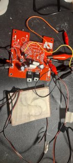
I am struggling to find the issue for days and i have soldered/disoldered to test different stuff, so that's why the board looks like frankenstein!
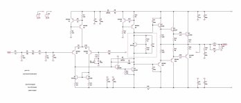
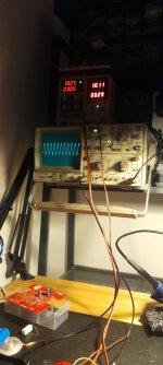
Anyway, i have attached scope meaurements, pcb layout/schematic.
If i have made an obvious mistake or you have encountered a similar instability issue it would realy help me.
Thanks in advance!
Best regards
Patsaoglou P. GR
I decided to design a 30W RMS 2 channel amplifier using smd components for the input,the vas, the driver stage and the mje15028/29 bjts for the class ab output stage. For the input stage transistors i have used the dual bjt in package transistors BC847/57BS, the bc847/57 for the vas, and the BCX53/56 transistors for the driver stage. I have set the gain to 27db and the miller cap to 120p. Tail current is set to around 2mA and the vas current to around 6mA. I have set the vbe multiplier to around 1V at the point before output transistors start conducting. Pi filters at the rails, the resistors are shorted because i didnt have the component on hand but no big deal.
I have soldered all the component by hand, and i have measured the current source resistors and they seem to be within spec. I also have soldered 2 boards to see if i have made a soldering mistake but the same issue.
The issue that i have is that when the output is not loaded the amplifier is outputting a nice and clean signal and within spec. Once i add a resistive load at the output , even a 100omhs resistors the amp loses stability and starts oscilating.
I also noticed that when signal is 0 and i have a load connected i have a stable few milivolts noise each second. Noted!
What i have tested:
1) tried to slightly increase the miller cap. no noticeable difference.
2) i have disoldered the output bjts and drive the output with the drivers as i can do that and see if it is mje issue. no difference.
3) applied load directly at output resistors to see if its feedback or an output trace inductance issue. no difference
4) i have added 100p caps by hand between output and various nodes. no difference.
I am struggling to find the issue for days and i have soldered/disoldered to test different stuff, so that's why the board looks like frankenstein!
Anyway, i have attached scope meaurements, pcb layout/schematic.
If i have made an obvious mistake or you have encountered a similar instability issue it would realy help me.
Thanks in advance!
Best regards
Patsaoglou P. GR
Attachments

I'll give a test once i make a zobel. Is there any other thing that could cause such an issue? i mean instability on loading could be cause by other reasons too? Thank youThere's one way to find out, but yes.
Your circuit seems to be marginally stable.
Perhaps including the emitter follower in the VAS Miller loop is the cause.
The output RL simply prevents capacitive loads from causing instability,
it does not improve the amplifier's inherent stability, and is more of a bandaid.
The output RL simply prevents capacitive loads from causing instability,
it does not improve the amplifier's inherent stability, and is more of a bandaid.
Instability generally comes from feedback loops when the 'phase margin' is not quite enough to keep it together, and it wants to turn into an oscillator.Is there any other thing that could cause such an issue?
I'm currently playing with simulations that avoid feedback on the output devices...
The easy way is to keep everything the same, unloaded, but drive a duplicate pair of (heatsunk) output devices that have no GNFB connection, and are simply there for driving the speakers.
So the amplifier feedback all works nicely with no interference from the speaker, with 'dummy' devices, just there to linearise them with the NFB, but the actual speaker drivers don't panic when the cone whizzes about etc. This is just my thoughts - but it's an idea, and it's DIY 😀
Or better still, just use a linear VAS and drive the followers from that, no duplicate transistors required. They are only followers anyway, they don't really need any special drive, they will just follow the VAS, according to their gain (consider darlingtons).
This little trick (zero feedback) also allows you to completely decouple the speaker ground from the signal ground, because there's no longer a GNFB loop from the speaker output to signal ground, to scold you.
I haven't tried this in practice yet, but it should result in a very stable amp 🙂
Looks similar with what I'm building.
No expert here but no zobel on the output asks for trouble.
Also your Vas if you clip the amp will behave weird and may also latch to rail. One diode in parallel with the Cdom would help.
4.7n in the input filter looks weird to me, maybe I misunderstand it.
- Bruno.
No expert here but no zobel on the output asks for trouble.
Also your Vas if you clip the amp will behave weird and may also latch to rail. One diode in parallel with the Cdom would help.
4.7n in the input filter looks weird to me, maybe I misunderstand it.
- Bruno.
Attachments
Tested driving vas directly from input stage same issue.Perhaps including the emitter follower in the VAS Miller loop is the cause.
Its logical but shouldnt it work without it good enough!?o expert here but no zobel on the output asks for trouble.
It is low pass @330MHZ4.7n in the input filter looks weird to me, maybe I misunderstand it.
Probably thats the case!Instability generally comes from feedback loops when the 'phase margin' is not quite enough to keep it together, and it wants to turn into an oscillator.
I alsocame across that rail latching but shouldnt that be an issue at clippingAlso your Vas if you clip the amp will behave weird and may also latch to rail
Thank you guys for the responses!!!
Did you also move the Miller cap from the emitter follower base to the VAS base?
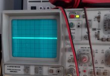
Guys! I removed feedback cap and i have much cleaner signal.
Still on the high end of the sine i see some HF!
Still on the high end of the sine i see some HF!
The VAS device really ought to have current limiting - or be in a beefier package, perhaps a SOT223. The SOT23 is rated for only 250mW which allows 7mA absolute maximum.
The amplifier uses CFP Complementary Feedback Pair in the output.
CFP is known to cause instability.
The cure is to put small caps between B and C on the drivers in the pair.
Say 47pF or 100pF.
CFP is known to cause instability.
The cure is to put small caps between B and C on the drivers in the pair.
Say 47pF or 100pF.
Instability generally comes from feedback loops when the 'phase margin' is not quite enough to keep it together, and it wants to turn into an oscillator.
I'm currently playing with simulations that avoid feedback on the output devices...
The problem is most of the distortion in a 3-stage amp is from the output devices and is very load-dependent, which is why feedback is needed in the first place - typical output stages are -70dB to -80dB distortion simulated and worse in real life (into loads), but with feedback -110dB is relatively easily obtainable at 1kHz (much harder at 10kHz). Various compensation schemes can help, which effectively reduce the influence of the output devices at higher frequencies which is kind of what you want - check out two pole and inclusive compensation schemes.
The Zobel and inductor are standard output networks for any such amp BTW. You can omit the inductor for short cables (for instance testing with a dummy load), but its a wise thing to include for generic use.
Those resistors looks like wire wound and therefore have additional small inductance, it looks like the resistors for the output stage are of the same dreaded types, use only film resistors here, which is even more important when having a CFP output stage.The issue that i have is that when the output is not loaded the amplifier is outputting a nice and clean signal and within spec. Once i add a resistive load at the output , even a 100omhs resistors the amp loses stability and starts oscilating.
This plus adding an RC zobel before the RL would be some of the first things to do.
- Home
- Amplifiers
- Solid State
- Amplifier loses stability on loading