Peter Daniel said:Where are the or series output resistors connected to?
speaker
I think we need to see more of the circuit to answer that question.....and all of those resistors in parrallel almost simulates an inductor to me
thylantyr said:Where is the best place to connect
the feedback resistor?
speaker
or B, if you prefer😉
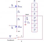
It's just a common amplifier design,
except for those 8 output series resistors. The feedback connects
to the output stage. I wonder what
will happen if you add a series
resistor to the output (for
short circuit protection) and I wonder
which end of the series resistor
is best to connect to?
8 series resistors = exaggeration,
assuming 40amperes of output current...
feedback
If you connect the feedback to the outside end of the series resistors, the feedback tries to control that point. That means it tries to compensate for the series resistors. So, you have the current protection, while at the same time in normal use they have no effect.
But at any rate, I think the combined resistance is too low to be effective anyway.
Jan Didden
janneman said:
..., the feedback tries to control that point.
Tells me its own tale. 🙂
JH
feedback
JH,
That's a very short reply! Not sure I get your meaning, though. I'm sure you know that I know that in a literal sense the feedback doesn't "try" to "control", of course. Care to elaborate?
Jan Didden
JH,
That's a very short reply! Not sure I get your meaning, though. I'm sure you know that I know that in a literal sense the feedback doesn't "try" to "control", of course. Care to elaborate?
Jan Didden
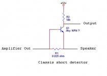
Hypothetical;
Referring the classic "transistor/series resistor" short circuit protection circuit,
if the output stage can deliver
20 amperes into a resistive load,
and I want to set my circuit protection to
20 amperes, then I do this?
0.7 volts / 20 amperes = 0.035 ohms
for the series resistor in order to
trigger the base/emitter of the
transistor.
That is about 14 watts of heat
for the resistor.
Would it be ok to parallel eight
.2 ohm series resistors (0.025 ohm),
each dissipating 1.75 watts vs.
getting one large 20w resistor ?
Would the wirewound resistor
inductance be low due to paralleling?
This is the reason I asked about
the feedback resistor. I want to
connect it to the correct location
on the pcb layout. So, it really
doesn't matter which side of
the series resistors I tap......
feedback
JH,
You made my day! It's nice someone agrees with you for a change.
Have a great day yourself.
Jan Didden
JH,
You made my day! It's nice someone agrees with you for a change.
Have a great day yourself.
Jan Didden
thylantyr said:[snip]0.7 volts / 20 amperes = 0.035 ohms
for the series resistor in order to
trigger the base/emitter of the
transistor.[snip]
What transistor?
Jan Didden
janneman said:
What transistor?
Jan Didden
Any bipolar will do ?
I used a cheap 2n3904 on
the test bench and charged
a 100,000 uf cap to 12v, shorted
the cap and transistor triggered.
Will this cheap transistor work in a power amp?
feedback
I mean, where is that transistor in your schematic? What is the actual circuit? It is difficult to discuss these things having no clue about the actual circuit.
Jan Didden
I mean, where is that transistor in your schematic? What is the actual circuit? It is difficult to discuss these things having no clue about the actual circuit.
Jan Didden
feedback
Yeah, any one will do, for pos currents. What will happen when there is a neg current?
Why not use R3 & R4 in your first schematic, much easier & cheaper. Use two transistors, an NPN and PNP for the two polarities.
Have you thought about what to do with the "output" of your transistor?
Jan Didden
Yeah, any one will do, for pos currents. What will happen when there is a neg current?
Why not use R3 & R4 in your first schematic, much easier & cheaper. Use two transistors, an NPN and PNP for the two polarities.
Have you thought about what to do with the "output" of your transistor?
Jan Didden
thylantyr said:Here is the generic circuit.
I guess I need a PNP version
to detect negative voltage ? (heh)......
(oops, typo, should say classic)
Hi,
power supply for this TUN must be +rail
anyway, your idea with additional resistor in output is not good. IMHO
jannemans idea is OK:
"Why not use R3 & R4 in your first schematic, much easier & cheaper. Use two transistors, an NPN and PNP for the two polarities."
Regards
Re: feedback
ah... the elegant solution..
I can connect a npn transistor (base/emitter)
across the source resistor (R3, .2 ohms) and it triggers
on 3 amperes of current flowing thru that resistor?
.7v / 0.22 ohms
I have a few protection circuits completed and somewhat
tested, I need to build the relay controller that accepts all the
inputs. I'm doing pcb layout on my reference board
for the stuff that I'm 90% works - heh, then fine tune
the pcb later.
janneman said:Yeah, any one will do, for pos currents. What will happen when there is a neg current?
Why not use R3 & R4 in your first schematic, much easier & cheaper. Use two transistors, an NPN and PNP for the two polarities.
Have you thought about what to do with the "output" of your transistor?
Jan Didden
ah... the elegant solution..
I can connect a npn transistor (base/emitter)
across the source resistor (R3, .2 ohms) and it triggers
on 3 amperes of current flowing thru that resistor?
.7v / 0.22 ohms
I have a few protection circuits completed and somewhat
tested, I need to build the relay controller that accepts all the
inputs. I'm doing pcb layout on my reference board
for the stuff that I'm 90% works - heh, then fine tune
the pcb later.
- Status
- Not open for further replies.
- Home
- Amplifiers
- Solid State
- Amplifier Feedback Resistor Location?