Hi ! How do you think, if we power up this Rotel amp (upper in posts) from smps and linear power supply, it will sounds the same ?What "standard measurements" are depends greatly on the area of the world and common in that industry. Even if you perform the same measurements with the same or similar equipment and conditions, interpreting the results can vary greatly with the people running the tests.
Last edited:
@Anatolii_A Try it and see. Or is that 'hear'? Hi-fi / Lo-fi synesthesia! 😉
I built a set of active filters a couple of years ago (I've mentioned this a couple of times). I tried a 'minimalist' approach, using resistor-loaded BC850s as buffers for unity gain Sallen-Key type filters. And they really did sound "transistor-ish". The various adjectives I'd heard people using about a "transistor sound" actually made sense. It was slightly grainy, gritty, with a little bit of an underlying "zing" to the sound. It was almost like a dud speaker panel with a faint rattle, but with perfect consistency and a bright metallic timbre to it.
My recollection changes over time, but it was a while before I was able to notice the distortion because it was quite faint. But once you've located it, you can't "unhear" it. For context, that was just what I was able to hear through the veil of the class-D chip amps I was using. Then I recognized the tone of our old Rotel. It was similar, but somehow softened. The imagery that comes to mind is that of a harpsichord, where the tone is softened because 3 strings are plucked at once, instead of just one.
On a certain level I think @cumbb and others are fundamentally right. If you listen to something for a long time, you don't want subtle annoyances. Which is ironic. Nobody would care about "wrong opinions" if it didn't touch a nerve on some level! If I'm honest with myself, I've spent hours at a time doing keyboard sessions, where I deliberately apply simulated overdrive distortion. It sets a certain mood, and of course I wouldn't want that as an overlay for everything. But I also noticed that the background annoyance level of that kind of distortion (in the wrong place) was lower than some of the more persistent transistor distortion.
I don't know how much of that makes sense from the outside. In my case, I would either leave a Rotel alone, or re-use the heat sinks. There's a thread (buried somewhere) on how to the improve the distortion by 20dB. But I get the feeling that most of the real distortion is being missed from a theoretical standpoint.

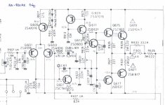
I always try to reply to the previous post, so let's look at tweaking the bog-standard and cheapish, old Rotel RA-820 AX amplifier, which I have thoughtfully looked up:
https://www.diyaudio.com/community/threads/improve-a-rotel-amp-thd-by-20db.275171/
The basic idea seems to have been to improve the differential input pair topology and faff around with earthing on the usual diode bridge power supply and taking more care with earthing:

Leading to this:

Also talk of replacing the NE5532AN op amps with FET input opamps with less DC offset, leading to less DC offset at the output in a preamp that might resemble this sort of RA-931:

I'm not sure I totally care, if you want a better amp, you buy a better amp!
Rotel certainly supplied enough options, but all with their lovely "Built like a tank" quality.

In fact they have always talked about "Balanced Design Concept", where you balance improvements in a price bracket:

I went bananas about my Rotel "Tower of Power" in the 1990's. Separate CD and DAC, power amp and preamp. Whole thing was groaning under its weight!
Sounded lovely, of course.

But when I moved home, I simplified it to "Good Enough":

Whole thing is endless. It's a Class AB Transistor setup, and that is what it sounds like. I enjoy it. I do however, detest Darlington transistor output stages. Terrible cheap things.
Since Transistor Amps like driving 8 ohms resistive, I spent time on seeing if I could build such a loudspeaker. Turns out you can:

Could I hear any difference. Not really. 🤣
https://www.diyaudio.com/community/threads/flat-impedance-and-flat-power-response-design.302001/
Best regards from Steve in Portsmouth, UK.
https://www.diyaudio.com/community/threads/improve-a-rotel-amp-thd-by-20db.275171/
The basic idea seems to have been to improve the differential input pair topology and faff around with earthing on the usual diode bridge power supply and taking more care with earthing:
Leading to this:
Also talk of replacing the NE5532AN op amps with FET input opamps with less DC offset, leading to less DC offset at the output in a preamp that might resemble this sort of RA-931:
I'm not sure I totally care, if you want a better amp, you buy a better amp!
Rotel certainly supplied enough options, but all with their lovely "Built like a tank" quality.
In fact they have always talked about "Balanced Design Concept", where you balance improvements in a price bracket:
I went bananas about my Rotel "Tower of Power" in the 1990's. Separate CD and DAC, power amp and preamp. Whole thing was groaning under its weight!
Sounded lovely, of course.
But when I moved home, I simplified it to "Good Enough":
Whole thing is endless. It's a Class AB Transistor setup, and that is what it sounds like. I enjoy it. I do however, detest Darlington transistor output stages. Terrible cheap things.
Since Transistor Amps like driving 8 ohms resistive, I spent time on seeing if I could build such a loudspeaker. Turns out you can:
Could I hear any difference. Not really. 🤣
https://www.diyaudio.com/community/threads/flat-impedance-and-flat-power-response-design.302001/
Best regards from Steve in Portsmouth, UK.
Attachments
This one?Hi ! How do you think, if we power up this Rotel amp (upper in posts) from smps and linear power supply, it will sounds the same ?
You could do a lot and significantly alter and also improve the sound.
Keep your toroidal transformer. More on this later.
Attachments

Need to understand that the main thing in any audio device is power source. Sound is born from it.Try it and see
It's a Class AB Transistor setup, and that is what it sounds like. I enjoy it. I do however, detest Darlington transistor output stages.
This seems to tie in with some of the observations in the 2nd half of this Pass Labs article on distortion . (Pay attention to the high peak voltages and high frequencies generated.) Assuming the output BJTs have the highest distortion, and they're driven by emitter followers with the next-highest distortion, each "layer" (it doesn't even have to be a gain stage, it can be a buffer) distorts the already distorted output of the previous part.
My thinking is that if you've committed to an output with 2-3 emitter follower layers, you're kind-of forced to follow the whole recipe with an op-amp gain stage to hopefully bring the IMD down to minuscule levels. A Sziklai / CFP does seem like a solid alternative. Or MOSFETs.
I kind-of resent Douglas Self for short-changing readers with his false claims that MOSFETs have high distortion and low gain. They are transconductance devices and the current gain is very high, even accounting for capacitance. We could've had nice things, like a variety of different lateral MOSFETs to meet the needs of the audio market. But no.*
~~~
Then there are the power rails, which, in the case of class-B or lightly biased AB, have to handle highly-distorted garbage from the transistors doing their half-wave switching. Not to mention, heavy, differential loading. The loads on the + and - rails oscillate in sequence, not simultaneously.
So as you can see, a long-tail pair could get very messy: +V is doing one thing and -V is doing something else. And there's likely a ground reference as well, coming from a transformer's centre tap.
It makes sense that manufacturers have a product range, and a sort-of square law for price vs quality. You can't double the size of the PSU and not put more watts on the brochure. Then the serendipity where various modulations from the signal go down, as rail voltage goes up. But to chase those "easy gains", you have to rework the design for higher voltages, and basically make sure the last 10% of the engineering work doesn't cost more than the first 90%. 😆
*Maybe it was some inside joke, and another author wrote that "bipolar transistors are basically unsuitable for audio amplifier output stages, due to their low current gain and second breakdown", or something like that, and it went over my head. I don't know...
Last edited:
Hi abstract,
Mosfets have lower transconductance than bipolar devices. This is factual, Douglas Self merely pointed out the truth. I find most designs that use Mosfet outputs aren't designed properly and the focus seems to be on a lower cost amplifier. Note I said most designs and not all. Your comments towards Douglas Self are unwarranted and come from a place of a lack of understanding.
Please note that theory and practical realization often differ. This is especially true with simulation drivers. Real world layout and component behaviour is often not well modeled, nor are thermal effects. Exact component values are often ignored and set to a perfect value which does not represent reality. Therefore, you can't compare actual performance of circuitry past a rudimentary level with simulators. You also must allow experience to provide a sanity check over what the computer program spits out.
Nelson Pass is a gifted engineer and one heck of a great guy. However, he will tell you his design directions follow his interests and not necessarily the highest performance. He is a master at extracting the best performance with the fewest parts. This path isn't the best for low distortion, but if you like that sound of those designs, and the concepts behind them - great!
Hi Anatolii_A,
Careful with comparisons. You must ensure each behaves properly, otherwise you have introduced uncontrolled variables in your experiment resulting in a complete waste of everyone's time.
Power supply noise and performance are important - to a point. Once you are beyond a certain performance level, further improvement does not change anything at all. It's the same with everything, you improve performance to a point beyond which you are wasting money. That is called engineering. The system will never perform at a level past the weakest part of that circuit or system.
When I improve the performance of an audio device or piece of test equipment, I do look at the power supply and especially regulator circuits. Sometimes improvements can be made, sometimes not. One thing for sure, improving these things takes knowledge and experience. You are not normally going to read what you need to know on the internet or in forums.
Mosfets have lower transconductance than bipolar devices. This is factual, Douglas Self merely pointed out the truth. I find most designs that use Mosfet outputs aren't designed properly and the focus seems to be on a lower cost amplifier. Note I said most designs and not all. Your comments towards Douglas Self are unwarranted and come from a place of a lack of understanding.
Please note that theory and practical realization often differ. This is especially true with simulation drivers. Real world layout and component behaviour is often not well modeled, nor are thermal effects. Exact component values are often ignored and set to a perfect value which does not represent reality. Therefore, you can't compare actual performance of circuitry past a rudimentary level with simulators. You also must allow experience to provide a sanity check over what the computer program spits out.
Nelson Pass is a gifted engineer and one heck of a great guy. However, he will tell you his design directions follow his interests and not necessarily the highest performance. He is a master at extracting the best performance with the fewest parts. This path isn't the best for low distortion, but if you like that sound of those designs, and the concepts behind them - great!
Hi Anatolii_A,
If the performance and noise of those power supplies were the same, you would not hear a difference. Not unless you were negligent in controlling RF noise.How do you think, if we power up this Rotel amp (upper in posts) from smps and linear power supply, it will sounds the same ?
Careful with comparisons. You must ensure each behaves properly, otherwise you have introduced uncontrolled variables in your experiment resulting in a complete waste of everyone's time.
Power supply noise and performance are important - to a point. Once you are beyond a certain performance level, further improvement does not change anything at all. It's the same with everything, you improve performance to a point beyond which you are wasting money. That is called engineering. The system will never perform at a level past the weakest part of that circuit or system.
When I improve the performance of an audio device or piece of test equipment, I do look at the power supply and especially regulator circuits. Sometimes improvements can be made, sometimes not. One thing for sure, improving these things takes knowledge and experience. You are not normally going to read what you need to know on the internet or in forums.
Maybe I used the wrong word. I did mention current gain. Parasitic capacitance is often mentioned, but most of the heavy lifting is done in the bass. Besides, he is selectively judging individual devices without looking at their role in a system.Mosfets have lower transconductance than bipolar devices. This is factual, Douglas Self merely pointed out the truth.
His interests vs the highest performance?Nelson Pass is a gifted engineer and one heck of a great guy. However, he will tell you his design directions follow his interests and not necessarily the highest performance. He is a master at extracting the best performance with the fewest parts. This path isn't the best for low distortion, but if you like that sound of those designs, and the concepts behind them - great!
See, I could guess that his interests are exactly aligned with the highest performance. But your definition of 'performance' may be biased differently, leading you to see his interests as misaligned.
You seem to be erroneously trying to reduce THD and similar metrics to something like a distortion 'IQ' number. Have you seen 2 different amplifiers with the same THD but completely different harmonic content? Did you prefer one over the other? A kind of bias that you may have, is that if you find out the specifications before you've had a chance to test with your ears, you may end up doing negative training, and disciplining yourself not to prefer one over the other, even though your ears are trying to tell you that you missed some important technical variable.
An interesting test would be to de-tune both amplifiers, blindly, so: just listening without looking, and try to get them equal to each other. Then measure the resulting distortion of both. And you will see with your own eyes, that X amount of THD is subjectively equal to a possibly very different Y amount of THD from the other.
Performance acquires a relation to a property, or to some. I mean, the sound will be the property to be mentioned;-)
Nelson cuts quite a good figure;-)
At least this one doesn't make the mistake of turning two different sounding ones into four different sounding ones: "double mono"-)
Nelson cuts quite a good figure;-)
What is certainly not written on internet or in forums and textbooks: same parts sound different. This Rotel power amplifier has, strictly speaking, two power supplies. Positive and negative. The ear already perceives these two as different: more noisier, dirtier, rumblier and more overcast than just one power supply.You are not normally going to read what you need to know on the internet or in forums.
At least this one doesn't make the mistake of turning two different sounding ones into four different sounding ones: "double mono"-)
You wrote rather a lot, so I'll just pick out this part if I may:Remember, feedback happens instantly in audio terms.
If everything is instant, why is stability ever an issue?
How do we create an oscillator if time is irrelevent, and everything in instant?
I'm not saying that the speed of the electric wave (thought to be C, the speed of light, or similar), takes time, my concern is the speed of an impulse to make it from the front of an amplifier to the back, shich surely must be there, in order for stability to ever be a concern?
Hi abstract,
I have serviced a all types of amplifiers for many decades, from both a warranty service and out of warranty perspective. I also design them. Mosfets have their characteristics, bipolar types their own. I find mosfets better for active regulators, bipolars have lower distortion than the mosfet types using the same voltage amp and feedback ratio in amplifiers. This is purely a function of output stage linearity. The second breakdown inherent in bipolar transistors means you have to use more of them for the same dissipation, but mosfets have some breakdown mechanisms as well. I'll opt for a more linear output stage, thank you very much.
Gate capacitance makes a mosfet more difficult to drive as the frequencies increase, but if you design a proper driver stage it isn't a problem. Most designs do not provide a high enough current drive capability, gates are only really high impedance at DC and low frequencies. Vertical types also have a gate charge characteristic, and that is a problem for linear applications.
I've had in person conversations with Nelson. I understand perfectly well where he is coming from. Don't try to read more into what I said than there is please. I have great respect for the man.
Yes, many amplifiers can have the same distortion NUMBERS, but a completely different spectrum. I have said this many times, I won't answer that question again. What I have found works in practice throughout a large population of people over a long time period.
I have also said that I don't assess my own work. I take before and after measurements every single time. Bias levels are set both static and under load (driven). I don't have to learn anything over as I've always kept a curious, open mind and follow the evidence. Testing to "detune" different amplifiers is pointless as they don't all react the same way. You've introduced a bunch of variables that make testing pointless. When you design a test, you must make sure you eliminate all variables except what you want to test. There is skill involved in designing any test. Do it wrong, your results are invalid and may well mislead you. I do test some output stages open loop, without any feedback. A Stasis output stage only has feedback from the driver stage for example. They have their own characteristics, and I do own a receiver with a Stasis output stage.
Also, subjectivity can and often does vary from day to day. Humans are terrible test instruments, so measured response is a very useful guide. At the level of my current test equipment, measured response agrees with subjective comments. A great indicator that all is well. Better test equipment does exist and many skilled in design and test have it.
Hi Globulator,
Instability occurs at much higher frequencies than the audio band with good amplifiers. They can oscillate from 150 KHz to over 1 MHz. A very well known stability issue. It concerns phase margin. So what you are talking about isn't an issue at the low audio frequencies. Please read up on it.
Instability occurs at much higher frequencies than the audio band with good amplifiers. They can oscillate from 150 KHz to over 1 MHz. A very well known stability issue. It concerns phase margin. So what you are talking about isn't an issue at the low audio frequencies. Please read up on it.
You wrote rather a lot, so I'll just pick out this part if I may:
If everything is instant, why is stability ever an issue?
How do we create an oscillator if time is irrelevent, and everything in instant?
I'm not saying that the speed of the electric wave (thought to be C, the speed of light, or similar), takes time, my concern is the speed of an impulse to make it from the front of an amplifier to the back, shich surely must be there, in order for stability to ever be a concern?
Phase shift takes time to build up to its steady state value, due to the free or homogeneous response of the circuit system.
https://ocw.mit.edu/courses/2-003-m...08c2c0d57d1d0c79d97f7aa_NotesInstallment1.pdf
Propagation delay in audio circuits is not normally a problem, being on the order of nanoseconds.
Circuits can be unstable at low (subsonic) frequencies as well, and most who have built or repaired tube circuits have seen this.
Performance acquires a relation to a property, or to some. I mean, the sound will be the property to be mentioned;-)
Nelson cuts quite a good figure;-)
What is certainly not written on internet or in forums and textbooks: same parts sound different. This Rotel power amplifier has, strictly speaking, two power supplies. Positive and negative. The ear already perceives these two as different: more noisier, dirtier, rumblier and more overcast than just one power supply.
At least this one doesn't make the mistake of turning two different sounding ones into four different sounding ones: "double mono"-)
I certainly don't question your knowledge of SRT (Special Relativity Theory, not SR Toothpaste I suppose) and why it is wrong. I presume you are referring to that unscientific charlatan Einstein, who admitted to making mistakes.
But surely Rotel know what they are doing with this dual-rail power supply? If one rail good, surely two rail better;-)
I am a simple old electronics engineer, and must be missing something? Do explain, preferably in clear English;-)
I'm guessing that each amplifier has a frequency at which it would oscillate, if the gain was above unity at that frequency.Propagation delay in audio circuits is not normally a problem, being on the order of nanoseconds.
Circuits can be unstable at low (subsonic) frequencies as well, and most who have built tube circuits have seen this.
Some amplifiers with marginal stability use to 'ring' a little, which can be audible.
Good amplifiers don't ring. But could there be a point where even though the phase shift is very safe, it still moves a little, enough to affect the imaging?
I agree about the LF stability. In my experience in SS, too large a capacitor on the LPF of the feedback path (a series cap and resistor to ground) cuts off too much LF and the DC offset correction can't react fast enough to cancel meandering DCish inputs, so the output offset gets pushed around like a drunken sailor. In this case vinyl rumble gets the amplifier very giddy indeed...
You have to learn to distinguish between object and concept first!I certainly don't question your knowledge of SRT (Special Relativity Theory, not SR Toothpaste I suppose) and why it is wrong. I presume you are referring to that unscientific charlatan Einstein, who admitted to making mistakes.
But surely Rotel know what they are doing with this dual-rail power supply? If one rail good, surely two rail better;-)
View attachment 1379449
I am a simple old electronics engineer, and must be missing something? Do explain, preferably in clear English;-)
If you still want to warp circuit diagrams supposedly: the circuit diagrams remain unchanged;-)
Hi Globulator,
Yes, each amplifier circuit will have some frequency where the phase reverses and if it still has enough gain at those frequencies it will oscillate. If it is marginal, it may ring, but again this is well above audible frequencies. However the effects of high frequency oscillation and maybe ringing often show as increased distortion or more supply hum. This can happen very commonly when outp[uts are changed with different device numbers and care is not taken to re-compensate the amplifier. I have even seen this with STK power modules back in the day when the exact same part was used as a replacement from authorized channels.
A larger feedback path to ground capacitor does the opposite. It will extend low frequency response. When they lose capacitance or a smaller one is installed, they will cut off low frequency response. LF instability is most probable with DC servos. If the amplifier hunts at very low frequencies, it is unstable in other ways. So a design fail. The LF cut has nothing to do with that except interact with the problem. Allowing gain at DC is really not advised.
Record warp induced problems would be the fault of the phono preamp and possibly bad arm-cartridge combination. Record warps being obvious issues. There is no music at very low frequencies below 20 Hz on records, a -18dB/oct high pass filter is common with good equipment. Sometimes it is switchable after the phono preamp.
I think I finally found the phrase I was looking for, from the digital world: 'Rise time' 🙂If it is marginal, it may ring, but again this is well above audible frequencies.
This is the delay I mean, not any actual temporal division within the netlist, but the time for a signal at the input to reach a decent threshold at the output 🙂.
So if an amplifier is non-linear and has a finite rise-time, I think there may be some non linear phase shift of the HF, in some amplifiers. Hence affecting the imaging.
I.e. If there are imaging differences between amplifiers, I think it's likely due to phase shifts moving the perceived location of the sound around the soundstage. And the FR too perhaps.
I had the LF instability on a Maplin MOSFET amplifier when the input cap was increased and the LPF feedback capacitor was increased from 47uF to 330 or 470uF (can't recall now LOL, it did simulate better 😀 ), and watched the woofer cone wandering about trying to catch up.
I.e. more LF got into the amplifier, and the GNFB servoing was too slow to keep it under control.
I still have to change that capacitor back to 47uF actually, currently the fix is to switch the 15Hz rumble filter on, currently easier than dissassembly and buying new caps - but it will get done 😀.
The LPF allows full negative feedback at 0Hz - LowHz, as a servo for the offset.
The phono amp is an old Sony one so that's sort of fixed, but the Maplin amp LF instability is my fault LOL, a 10uF input cap and bigger LPF cap tipped it over the edge - philosophically I feel the amplifier should be (and probably was) immune to dodgy inputs 😀
It's got quite nice imaging though - but that's the HF I think, not the LF !
Can you tell if something has moved backward or forward one INCH in the image? And how much phase shift does one INCH correspond to at 20 KHz? More than in any amplifier I’ve ever seen, even one that’s oscillating. Speakers, unlike amplifiers, however, are non minimum phase systems.
- Home
- Member Areas
- The Lounge
- Amplifier design and stereo imaging