I know I am late for the party, but I wonder if you or anyone did make this amplifier?
After looking at the KCP amplifier previously referred to, I wanted to make one. But I couldn't figure out how to make it complete...
Is the original KCP amp only an 0dB OPS, needing an IPS? With or without global feedback?
Here is what I have done so far:

Original schematic, I think:

Thanks for any answers!
🙂 morten
After looking at the KCP amplifier previously referred to, I wanted to make one. But I couldn't figure out how to make it complete...
Is the original KCP amp only an 0dB OPS, needing an IPS? With or without global feedback?
Here is what I have done so far:
Original schematic, I think:
Thanks for any answers!
🙂 morten

The GNFB is taken on top of 0.22 Ohm. The GNFB approach looks like MF-A1, but it could only be used as a unit buffer. I don't think it is worth your time to build it.I know I am late for the party, but I wonder if you or anyone did make this amplifier?
After looking at the KCP amplifier previously referred to, I wanted to make one. But I couldn't figure out how to make it complete...
Is the original KCP amp only an 0dB OPS, needing an IPS? With or without global feedback?
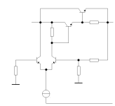
There is feedback via Q3 and Q4.
It's a unity-gain voltage follower meant as an amplifier output stage with a very subtle distortion compensation method in it. It is described in detail in Kendall Castor-Perry, "Look, Ma, No Distortion! The Class i output stage", Linear Audio vol. 2, pages 65...88, September 2011. Don't ask me how it works, as I never really understood it.
It doesn't seem to have anything to do with post #1, nor with the thread title, so I wonder why it is in this thread.
The amplifier in post #12 is applying feedback individually to the two complementary halves. The purpose seems to be to regulate the bias (note that there is no Vbe multiplier).
I don't believe a class AB amplifier can ever be made distortion-free. Even if the crossover can be done perfectly, any mismatch between the complementary halves will produce even-order distortion.
(I don't have access to the article).
Ed
I don't believe a class AB amplifier can ever be made distortion-free. Even if the crossover can be done perfectly, any mismatch between the complementary halves will produce even-order distortion.
(I don't have access to the article).
Ed
MarcelvdG: This amp by KCP was referred to in #7.
Ah, I see. It might be useful for you to ask for a thread split at post #12 anyway, and to suggest a new title that makes it clear that it is about Kendall Castor-Perry's class i output stage. Maybe some class i expert will chime in then.
Most of what is in the Linear Audio article is also in the freely accessible EDN articles dreamth linked to:
https://www.edn.com/designing-a-low...roduction-the-problem-with-push-pull-outputs/
https://www.edn.com/the-class-i-low-distortion-audio-output-stage-part-2/
I finally understand dreamth's association between the thread title and class i: the distortion compensation method in a class-i output stage ideally leads to a small, predictable and signal-independent output stage output impedance.
Last edited:
The EDN links load sporadically.
This is a non-switching amplifier. The reduction in distortion is due to feedback. The output transistors' emitter resistors are outside of the feedback loop.
Ed
This is a non-switching amplifier. The reduction in distortion is due to feedback. The output transistors' emitter resistors are outside of the feedback loop.
Ed
The EDN links load sporadically.
This is a non-switching amplifier. The reduction in distortion is due to feedback. The output transistors' emitter resistors are outside of the feedback loop.
Ed
Indeed, but with separate feedback loops around the push and pull sides that gradually go from voltage follower behaviour to current source behaviour, designed such that they complement each other very well.
I guess the usability of the class i voltage follower as an output stage in an amplifier with overall negative feedback will depend on how wideband the class i circuit can be made, as its poles and zeros affect the overall feedback loop. Of course the same holds for the more conventional voltage followers that are usually used as output stages (such as Darlington emitter followers and Sziklai pairs).
I have also been experimenting with this concept and made various changes to create a working prototype.
The prototype includes a voltage amplifier and overall feedback to make the output impedance low.
The tests on the prototype used an unregulated power supply:-
Voltage gain at 1 kHz = 19.5, 27.7 dB.
Small signal frequency response 3.7 to 255 kHz.
Power bandwidth to 1 % distortion, 8 ohm load, 58 kHz.
Slew rate 11.5 V/us
Harmonic distortion, 8 ohm load, 40.5 W:-
1 kHz, 0.006 %.
20 kHz, 0.03 %
Output impedance, difficult to measure with accuracy, but my best attempt was 6 mohm at 20 kHz, measured at the feedback take off point on the PCB.
The distortion performance is mediocre but cross over distortion is low because the output stage doesn't switch and the transition between supplying output current and idling is smooth. Most of the distortion appears to be due to the non-linearity of the voltage amplifier.
Attachments
Hello M0rten, Thanks for your interest. In my first post I attached an LTspice XVII file that contains the following schematic.

You can look here for some more https://www.diyaudio.com/community/threads/class-i-and-siblings.202684/
This means that the preset (or automatically set) offset voltage ensures an initially constant DC current flow through the actual emitter-follower output stage.The GNFB is taken on top of 0.22 Ohm.
It may not be immediately recognizable at first glance, but like Tim de Paravicini's MF-A1, it is (at its core) a simple, rudimentary voltage regulator. The reference voltage is the reference potential of 0V (or GND). However, the A1 is a rail-to-rail controller, i.e. it can burn out more easily without additional protective measures.The GNFB approach looks like MF-A1,
Just like the A1, an approach such as the one presented here can also be provided with an ac-active negative feedback. In other words, with an ac-gain > 1.but it could only be used as a unit buffer. I don't think it is worth your time to build it.
The reason why the call for
Abkopplung
has been heeded cannot be seen in the context of absolutely unrelated nodes. Morten's excursion would have technically fitted in very well with the original thread.
HBt.
Attachments
Last edited:
The gimmick is the coupling of the virtual output zero (through Q2 & Q6) to the input of the entire symmetrical control loop.
Complicated only at first glance. The interaction of + & - feedback can be tuned in such a way that the amplifier has a predictable internal resistance “in the sense of the original thread”, i.e. it can be regarded as a voltage-controlled current source - but not necessarily must!
Complicated only at first glance. The interaction of + & - feedback can be tuned in such a way that the amplifier has a predictable internal resistance “in the sense of the original thread”, i.e. it can be regarded as a voltage-controlled current source - but not necessarily must!
- Home
- Amplifiers
- Solid State
- Amplifier based on the Kendall Castor-Perry's Class I output stage