Hi,
ive got a pair of these Ampex 612 or 620's, and would like to get them sounding a little better. (they're labeled as 620's, but match the 612 schematic)
Basically, it looks like they used to have a tone control, and someone has removed it, and sort of butchered the feedback circuit. I redrew the schematic as mine have been modified, but I can't find my drawing anywhere! I'll have to take a look at them tonight and redo it.
I'll attach the 'stock' schematic here.
The issue I'm having is that they are very high heavy.
also, there is much more going on in this schematic than any of the schematics I've seen posted here as being a "good" P.P. amp.
If anyone has a few minutes and is bored, could you look at this schematic, and tell me how I could modify these to sound better. I don't really want the tone control on them at all. I'm afraid I don't know enough about amps at this point in time to know what is going on w/ the feedback.
I did disconnect the nfb all together, and it sounded bad.
Other than being high heavy, I think they sound great! If I connect them to some bass heavy speakers, or add a powered sub to fill in the low end, they're perfect.
I guess I should add that they aren't in their original cases, and don't have the speakers they originally come with. I've built them into a nice modern looking chassis. At this point, there's no reason to keep the amps stock, for historic reasons.
Attachments
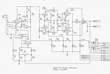
That looks like a Mullard style circuit, with the tone control stuff inside the NFB loop. Bad sound after disconnecting the NFB circuitry is not surprising.
You did say simplify. How far are you willing to go? Could you live with 6 W. of O/P from triode mode, as opposed to 15 W. from pentode mode?
You did say simplify. How far are you willing to go? Could you live with 6 W. of O/P from triode mode, as opposed to 15 W. from pentode mode?
A complete rebuild is an option I was thinking about. As long as I can use the same tubes, and obviously transformers.
I only found a couple of 'hi-fi' 6v6 schematics, and they were completely different than this amp.
What's the purpose of the first tube in this schematic? Is that splitting the input to the upper and lower tubes? I ask, because most of the schematics I've seen do not have that stage.
I think I could live w/ 6 watts. It's a tough decision. I got a single ended triode amp, so do have the speakers for it, but more power would be nice........
A major simplification of the feedback circuit would be nice too.
At this point, however, I'm not sure which components are boosting the treble, and which the bass, and how to figure out how much feedback to apply.
Everything I've been reading so far has been about single ended amps w/ no feedback.
I've got to start over now to learn about P.P.
So, a straight forward answer to what I should do w/ these amps is certainly welcome.
If there's a website out there that goes into the different aspects of these amps, a link to it would help too. (a link besides the search button here 🙂)
What would be great is a site that breaks the circuit into its components and explains each section!
Actually, I have seen a site like that. I try to find it again.
I don't know the heater ratings on your power transformer, but just for the fun of it, try using 6L6GC's instead of the 6V6's. It won't hurt anything to try them for about 10 minutes. It may tax your 6.3volt tap if used for more than a half an hour, and may get a little warm. I use 6L6's on my maggie amp but I'm also not using the tuner/preamp so my milliamps is about the same. 6L6's are the same pinout as the 6V6, just higher voltage ratings.
That NFB loop is confusing, I agree. To remove the tone control, you could replace the feedback network with a straightforward resistor, i.e. replace C11, C12, C14, R9, R13, R14, R15, R16, R22 and S1 with a resistor that goes from the spkr terminal to the cathode of V1. Try a value of 15k for the feedback resistor. If the amp is too sensitive, you can reduce the resistor to taste and/or strap V1 as a triode (see later).
It's a bit more complicated than that, though, because the more feedback there is, the greater the risk of HF instability. There almost certainly needs to be a capacitor in parallel with the feedback resistor. A 'ball park' figure of 100pF to 330pF might be suitable, but its exact value depends on the characteristics of the output transformer and no rule of thumb can be used. A square wave generator and oscilloscope are normally used to test the HF stability, and the capacitor is selected to give a clean 10kHz square wave at the speaker, without overshoot/ringing or round-shouldered appearance.
To explain the purpose of the first stage: it is a voltage amplifier that provides most of the gain. It may prove to have too much gain for the requirement and it might work better strapped as a triode, i.e. connect the screen directly to the plate and remove C2 and R5.
The phase is split by the 12AU7. Its plate loads R17 and R18 are unequal (100k and 120k) to compensate for the fact that there is a resistor (R2) as a common cathode load instead of a constant current sink. However, the difference of 20% in plate resistor value is unusual; 10% is more common.
I realize you prefer to use the same tubes but the 12AU7 is not a good one to use in any audio application and a 12AT7 would be much better.
A website that might help you analyze the amp on a stage-by-stage basis is Max Robinson's 'Fun with Tubes'.
Thank you guys so much! I was thinking of trying some of the things you've suggested, but being new to all of this, I'm still sort of afraid to just jump in and start changing things, w/out some advice first. Now that people who know what they're doing say to give it a shot, I think I'll warm up the soldering iron 🙂.
It's nice that they are mono blocks, so I change one, and compare the two.
Ok, I've got one more really really basic question, and it might fill in the gaps enough for me to finally understand what is going on.
I tried searching for the effects of networks of resistors and capacitors. Wikipedia was some help, but..... not enough.
I sort of figured out the tone circuit, in that I understand that the capacitor will attenuate the highs, the resistor will attenuate the lows.
I was wondering what the resistor/capacitor's in parallel are doing, but Ray may have answered that for me. The resistor is just lowering the power, and the capacitor is filtering some of the highs. (is that right?) (and here I'm talking about in the feedback portion of the circuit)
Then what's going on at the plate of the input tube, where the B+ goes through a resistor paralleled w/ a capacitor+resistor?
Then again, on the cathode of the 6v6's, there's a resistor and capacitor in parallel connecting to ground.
Wikipedia's explination of resistors and capacitors in parallel simply explains "The parallel configuration is generally of less interest to us" then gives some math... it never says what it's used for! I suppose the math is all someone w/ some E.E. training would need to understand it, but unfortunately, that's not me.
I guess my problem is that I understand the big picture, but not the basic EE details.
Thanks a lot!!!!!
A capacitor in parallel with a resistor can be used as a low pass filter. Consider the case where that sort of arrangement connects the grid of a triode to ground. As frequency rises, the capacitor's reactance decreases. Eventually, the cap. shorts the resistor out.
I suggested triode wiring, because it avoids the issue of a regulated screen grid B+ supply for pentode mode and the lower power ensures that loop NFB gives you good bass extension, without O/P trafo core saturation risk.
Superior performance from pentode mode O/P tubes really requires that screen grid B+ be regulated. More linear operation is achieved. In particular, IM distortion (NASTY) is reduced.
Too large an error correction signal in the deep bass, from loop NFB, can cause the magnetic headroom of the O/P trafo core to saturate. Between filtering infrasonic noise at the amp's I/P and limiting power O/P, saturation of the O/P trafo core will be avoided.
Dave Dlugos (Planet10) was kind enough to mention "El Cheapo". You could easily turn those monoblocks into "El Cheapo" variants. The complete "El Cheapo" saga is here. Here's a "deep" link to the schematic.
A capacitor in parallel with a resistor can be used as a low pass filter.
I think Eli means a high pass filter. The reactance (AC resistance) of a capacitor is lower at higher frequencies. The uses of a cap are many and varied. Caps are used, among other things, to block DC between stages, to apply smoothing in power supplies, to provide a low-impedance path to ground for audio signals in a cathode bias circuit, to provide frequency-dependant filtering in tone-control circuits, to provide delays, to set time constants, and many more.
The cap I suggested adding in parallel with the feedback resistor will have the effect of reducing the impedance of the feedback path, i.e. applying more negative feedback, at higher frequencies, to offset the peak in gain that usually occurs and can cause poor performance/instability at high frequency.
I strongly suggest that you visit Max's website and have a good poke around, to understand more about what's going on. Max is a retired lecturer in electronics and has made an effort to make his website educational in a 'user-friendly' non-academic way.
If you're interested in having a good book that explains many things for the tube hobbyist without too much mathematics, you could buy Morgan Jones's excellent Valve Amplifiers. You can buy it from Amazon.com
wicked, if your experience is limited, a complete rebuild is going to be frustrating. And the Mullard circuit is actually a very good one- in the Morgan Jones book mentioned by Ray (and I can't recommend that book highly enough- you need it), there's a complete analysis of the circuit and a good discussion of the strengths and weaknesses.
If it were my amp, I'd regulate the screens (use a Maida reg), change the 12AU7 to a 6GG7/6FQ7, put a CCS in the tail of the phase splitter, and make the two plate resistors of that stage equal, and return a feedback resistor to the EF86 cathode. At that point, you'll have a pretty fine amplifier. If this is gibberish, I assure you that once you're through the Jones book, this will seem simple and obvious.
If it were my amp, I'd regulate the screens (use a Maida reg), change the 12AU7 to a 6GG7/6FQ7, put a CCS in the tail of the phase splitter, and make the two plate resistors of that stage equal, and return a feedback resistor to the EF86 cathode. At that point, you'll have a pretty fine amplifier. If this is gibberish, I assure you that once you're through the Jones book, this will seem simple and obvious.
Thanks again!
I have been reading the 'Fun w/ Tubes' site for the past couple of days, and yes, that is a great site. Exactly what I was looking for to get started.
This hobby started off as me wanting to build a nice amp quickly, and Tubelab made that too easy 🙂. Now I want to start doing more, so buying the book is certainly a good next step.
Last night I was thinking about running the input tube, ef86 in triode, as well as the 6v6's.
I can't decide if I want to sacrifice all that power. I have a 6 or 7 watt triode SE amp right now. On one side, it would be nice to leave this P.P. amp w/ more power. On the other hand, it would be a fun comparison to hear the difference between a SE and a PP w/ the same output power.
Then in all honesty, all I really want is for the highs to be less extreme, and that would be a simple modification of the feedback, and the least amount of effort of all of the options.
Well, I guess I have a lot more reading to do before I jump into this project.
Thank's for everyone's replies, the link to the fun w/ tubes site, and the suggestion for the book!
Last night I had a dream that I had a big math exam coming up, and graduating depended on it. I'm sure is related to all of the reading Ive been doing w/ these amps lately. It was a huge relief to wake up and remember I've been done w/ school for 16 years!!!!!!!!!! (Tho, I'm bored w/ computers, my current career, and the idea of going back for an E.E. degree sounds kind of fun!)
I can't decide if I want to sacrifice all that power.
Dude,
Pentode mode "finals" will yield approx. 15 W. The Maida regulator SY suggested is an excellent idea. Remember, regulate screen grid B+ to get max. open loop linearity.
Pentode mode requires NFB to obtain an adequate damping factor. Unfortunately, this is where things can get sticky. A simple global NFB loop, as Ampex used, is likely to run afoul of O/P trafo core saturation, unless you limit bass extension. Your early remarks indicate that you want GOOD top to bottom balance. In order to obtain both the power and the linear bandwidth, some complexity will have to be introduced.
There is a short loop NFB technique known as plate to plate. Use of that technique, nested inside the global NFB loop, allows the outer, global, loop to apply only a few dB. and not unduly stress the O/P trafo's magnetic headroom. The "plate to plate" technique works best when high O/P impedance circuitry is employed in the phase splitter. Cascodes, instead of simple triodes, in the phase splitter will yield the desired high O/P impedance. To avoid extra tubes, FETs will be used in upper positions of the cascodes. Doug Piccard, AKA Bandersnatch, has experience with this style of circuitry and I hope he posts in this thread.
Do you make use of the mono volume control the schematic shows? That info. will help in making good recommendations. Another poster's remarks about the 12AU7 are (IMO) on target. Your thought of triode wiring the EF86 has merit, as you don't need "tons" of gain, when a CDP is the signal source.
Well,
I felt the need to heat up the soldering iron today, so I triode wired the ef86 and the 6v6 tubes. I removed the feedback.
I lost power, but the thing sounds great! It was a very simple modification.
A couple of friends and I had a listening test this evening between the unmodified channel, and the triode strapped channel. Other than the obvious loss in power, everyone agreed it sounded better.
I am not using a volume pot. I usually use a nice external sound card , or portable audio player (mp3 player, but I usually play lossess) as my audio source, and can control the volume there.
W/ everything triode strapped, it sounds quite similar to my 300b SET amp.
Whoever removed the original tone control and internal/external switch had things wired very strangely. They used all of the components which were in those circuits, but not in any order I could understand.
Maybe when I learn some more about NFB I'll be able to do it properly, and have it sound good in pentode mode.
I can picture a schematic for the NFB and FET/tube cascode you mentioned. Unfortunately, I don't know the math yet to figure out how to implement the circuit (component values).
It does sound like a good direction to take, and maybe that's where I'll focus.
hey-Hey!!!,
Here is a link to the triode/MOSFET cascode front end. It has been simplified a bit since its drawing. Namely using a voltage divider to ref the gates instead of driving current through a resistor. Cap on the R between cathodes and gates.
http://www.audioroundtable.com/GroupBuild/Projects/Merlin.pdf
It also uses a custom tapped output TX wound by Heyboer( based on an unwind of a Peerless S-265-Q ). Again, current edition has three taps, 20, 30 and 40%. If your OPT does not have taps, a resistor from the final's plates to the corresponding phase of the cascode will be needed in addition to the plate resistors from a decoupled supply. 60k FB resistors, and 30k plate loads perhaps?
cheers,
Douglas
we'll probably have to direct you to some cascode use research too...🙂
Doug,
I'd like to see the 12AU7 replaced. In Noval based, with a 300 mA. heater draw, the 12AT7 and 12AY7 seem to be the best matches. With a gm of only 1.75 mA./V., I have my doubts about the 'Y7 at the bottom of a cascode. With its gm of 6 mA./V., a 12AT7 set up at McShane's 200-220 V. on the plate and IB = 3 mA. will provide the necessary gain, working into a reasonably small plate resistor. It might be possible to use Mullard topology and replace the shared LTP cathode resistor with a CCS. A negative PSU rail would not be needed. 😉
Do you think the little ZVN0545A would pass muster in the hybrid cascode? ID = 3 mA. and not much voltage dropped across the FET is not particularly stressful.
Eli Duttman said:Doug,
I'd like to see the 12AU7 replaced. In Noval based, with a 300 mA. heater draw, the 12AT7 and 12AY7 seem to be the best matches. With a gm of only 1.75 mA./V., I have my doubts about the 'Y7 at the bottom of a cascode. With its gm of 6 mA./V., a 12AT7 set up at McShane's 200-220 V. on the plate and IB = 3 mA. will provide the necessary gain, working into a reasonably small plate resistor. It might be possible to use Mullard topology and replace the shared LTP cathode resistor with a CCS. A negative PSU rail would not be needed. 😉
I need to read and absorb more of this thread, but I have a couple thoughts:
The 12AT7 and a CCS in the tail a la El-Cheapo (thanks for the mention Dave!) would likely give enough gain to eliminate the EF86 entirely. And as Eli mentioned, about 210 volts/3-3.5 ma. or so is a nice spot for a 12AT7 driving push-pull finals.
It would also shorten the "length" of a global NFB loop.
I keep looking at the 6AX5s - not my favorite recto... If you replaced the recto with a couple good SS diodes and an inrush limiter you'd have a free trafo winding to play with. It could supply a B- voltage at a decent current level (even if voltage doubled) for whatever use. And the SS diodes would give you more B+. Maybe a choke could find it's way into the supply...
If I have anything to contribute I will after I do some more thinking.🙂
Jim,
Thanks for speaking up.
My initial thoughts ran towards "El Cheapo" too. This thread's originator wants max. power O/P and good behavior at the frequency extremes. Unfortunately, the O/P "iron" doesn't have UL taps 🙁 I'm disinclined to use the amount of NFB required by pentode mode "finals" solely in a global loop. IMO, that's asking for O/P trafo core saturation in the deep bass and may also create exposure to slew limiting from the HF error correction signal.
To hold the amount of NFB applied in the global loop down at modest levels, taking a page out of Stu Hegeman's book, and nesting NFB loops seems like the best thing to do. The "plate to plate" technique is (IMO) easier to get working properly than Hegeman's cross connected plate to splitter grid. "Plate to plate" works best in combination with high O/P impedance driver circuitry, hence the differential cascode in Mullard topology.
RE: the 6AX5 rectifier, installing a "hole shrinker" and switching to 6CA4/EZ81 should squeeze a few extra B+ Volts out. If Mullard topology is used, a negative rail is not necessary. ;(
Thanks for the replies!
I've got to tell you, though. I popped in a 12at7 which increased the gain. W/ everything wired triode, it's still putting out about 2x the power of my 300b set. (as far as my ears are telling me)
I may have enough power like it is now, and leave it all triode strapped for a while. It's more than enough for my existing speakers, even if it's not living up to its full potential.
From my reading, people say the ef86 is very linear in triode. I'm not sure about the 6v6's, but to my ears they sound good like this.
It's not AS good sounding as my 300b amp, but much better than it was!
Am I doing anything wrong w/ the circuit by simply removing the feedback, and triode strapping all the tubes? When switching to triode, do I need to change other component values to change voltages or current? I'm guessing not, because so many modern amp designs are including switches to switch between pentode/triode.
Thanks again! I'm sure I'll get bored and want to change these again in the future, so all feedback and pentode talk is not in vain.
Eli Duttman said:RE: the 6AX5 rectifier, installing a "hole shrinker" and switching to 6CA4/EZ81 should squeeze a few extra B+ Volts out. If Mullard topology is used, a negative rail is not necessary.
True, but it does make other options more easily accomplished. You could use a B- rail to implement combination bias on the 6V6s, which would offer more power and possibly some other advantages. 😎
I'm guessing not, because so many modern amp designs are including switches to switch between pentode/triode.
Switching between triode mode and ultralinear mode is usually "a piece of cake". Switching between triode and pentode is not nearly as straight forward. As you've seen from the "conversation", pentode mode has requirements quite different from triode mode.
From my reading, people say the ef86 is very linear in triode. I'm not sure about the 6v6's, but to my ears they sound good like this.
The EF86 is highly linear in both pentode and triode modes. The tube is simply superb.
When triode wired, 6V6 family tubes are incredibly linear. Go look at the curves for a triode wired 6V6. Those curves are as evenly spaced as those of the highly revered 6SN7. When you went all triode, end to end, with no NFB, the "weak sister" is the 12AU7. The 'U7 draws its share of flak for poor linearity.
- Status
- Not open for further replies.
- Home
- Amplifiers
- Tubes / Valves
- Ampex 6v6 PP Modifications