I also moved the heater jumpers above the board. It's so long ago, I don't remember if it reduced the hum level.
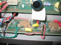
You can see that I chopped the board off, The rattling output tube caused a few problems, including an arcing socket, so I rebuilt the output section point to point. The cement block resistor at the top of the picture is also a replacement, a tube ran away and burned up the original resistor. I think I will eventually punch a new hole to the between the left power tube and the reverb send/receive cables and move the power tube that's next to the speaker over there.

You can see that I chopped the board off, The rattling output tube caused a few problems, including an arcing socket, so I rebuilt the output section point to point. The cement block resistor at the top of the picture is also a replacement, a tube ran away and burned up the original resistor. I think I will eventually punch a new hole to the between the left power tube and the reverb send/receive cables and move the power tube that's next to the speaker over there.
Attachments
Hi Dennis, I read most of the posts. I can see that without a spectrum analyser program then we are flying a bit blind when trying changes such as DC powering the filaments, and varying a humdinger. Some have been able to install an app on their phone and use that as a simple non-contact 'probe'.
I can see a concern with the battery test indicating not much change, and with the humdinger pot achieving some tuning performance.
The battery should be a good indicator, if it is grounded at a quiet point - you indicated the battery was grounded via the humdinger pot for that test. I guess I can see some uncertainty with respect to the heater grounding with battery - were you able to just power the input stage heaters only - and ground at the local stage 0V point?
The humdinger pot performance does indicate that the heater wiring has some noise on it getting to the input stage grids via capacitive coupling.
Your scope photo was probing a grid - that isn't a good place to probe - perhaps if you can probe on the junction of coupling cap and R13, or the top of the master vol pot, in order to get a good waveform. That scope waveform indicates you have a high frequency noise signal (???), plus some minor rectifier glitches plus some mains fundamental. Your scope probe ground lead could be aggravating what is being observed - which is where a spectrum of the speaker output via a microphone, or probing the speaker output, can help distinguish what noise signals are actually there.
Using UF4007 diodes, without bypass caps, may show up some improvement in that glitch. Your scope probe may have been introducing the glitch in to the plot - but I haven't checked what you said in the text.
Ciao, Tim
OK, but it doesn't tell me anything I didn't know already?
Here are the spectrums of the recordings I did before and after I moved the flying jumper. I was careful to put the mic in the same spot and tried to adjust the input gain about the same point, but that was "about 3 o'clock" so not very precise. All I can see is that the clutter in between the 60Hz harmonics went down a lot.
Here is before I moved the heater jumper wire.
 [/url]Spectrum of Ampeg noise before fixes by Dennis Kelley, on Flickr[/IMG]
Here is after re-routing the jumper wire.
 [/url]Spectrum of Ampeg noise after flying jumper by Dennis Kelley, on Flickr[/IMG]
The humdinger was installed with the center tap from the transformer heater winding disconnected. The 500 ohm pot's wiper was connected to ground at close to the same point the transformer center tap had been connected.
When I substituted the DC battery I left the pot where it was and adjusted the same as it was. I figured I needed it tied back to something.
This is the actual waveforms I recorded using a mic. The upper two traces are the before, and the bottom two are after the flying jumper. I had it setup to convert to stereo, is why there are two of each.
 [/url]Ampeg analog before and after by Dennis Kelley, on Flickr[/IMG]
Clearly you can see the waveform recorded by the mic looks a lot like the waveform seen by the scope. The after waveform, may not be correct. After I did that test, and decided I had fixed it, I had problems with the amp not working right. I thought I had broken something in the process of troubleshooting the circuit? I discovered a piece of wire i had used as a jumper to try and short out two node to isolate the signal. It was coming and going, and when I tried to turn the amp up it became intermittent. So i'm not sure if my quieter amp was due to the wire jumper or the shorting jumper I forgot I had installed, and was just shorting when I did the noise test, but then was not shorting when I ran the actual guitar through it. I think these are valid, but I'm not positive.
The results with the DC heater and the humdinger were all done after I found my shorting jumper.
I think I am on the right track. What amazed me was that it still hummed and buzzed, even with the DC heater voltage. But if the noise can get onto the 6.3 Vac through radiation, then it could just as easily get into the DC heater voltage. It can't be coming through the transformer like I thought it was, because the battery was not part of the transformer.
If I apply ground at the cap end of R13 I get no change. If I apply ground at the grid end of R13 the noise is silent. So it has to be this point that the noise is getting into the circuit. Maybe?
Oh, one more thing. Notice the higher frequency ripple on the analog waveforms? On the scope trace I saw a wide thick fuzzy waveform. Moving the scope probe around made this thicker or thinner, so I just assumed it was an artifact of the scope ground and stuff. But is this oscillation that I am seeing? That's what it looks like on the analog waveform? There is a place for a cap across the plate resistors of the tube that has the noise on the output. Right across R15. You can see it in the picture which shows the flying jumper I put in. i don't know why that cap is or isn't there. All I can find in my searches is it may be a way of making it not so bright, or of preventing oscillation. And for that matter why are there two resistors on the plate with the output signal being taken from between them?
Here are the spectrums of the recordings I did before and after I moved the flying jumper. I was careful to put the mic in the same spot and tried to adjust the input gain about the same point, but that was "about 3 o'clock" so not very precise. All I can see is that the clutter in between the 60Hz harmonics went down a lot.
Here is before I moved the heater jumper wire.
Here is after re-routing the jumper wire.
The humdinger was installed with the center tap from the transformer heater winding disconnected. The 500 ohm pot's wiper was connected to ground at close to the same point the transformer center tap had been connected.
When I substituted the DC battery I left the pot where it was and adjusted the same as it was. I figured I needed it tied back to something.
This is the actual waveforms I recorded using a mic. The upper two traces are the before, and the bottom two are after the flying jumper. I had it setup to convert to stereo, is why there are two of each.
Clearly you can see the waveform recorded by the mic looks a lot like the waveform seen by the scope. The after waveform, may not be correct. After I did that test, and decided I had fixed it, I had problems with the amp not working right. I thought I had broken something in the process of troubleshooting the circuit? I discovered a piece of wire i had used as a jumper to try and short out two node to isolate the signal. It was coming and going, and when I tried to turn the amp up it became intermittent. So i'm not sure if my quieter amp was due to the wire jumper or the shorting jumper I forgot I had installed, and was just shorting when I did the noise test, but then was not shorting when I ran the actual guitar through it. I think these are valid, but I'm not positive.
The results with the DC heater and the humdinger were all done after I found my shorting jumper.
I think I am on the right track. What amazed me was that it still hummed and buzzed, even with the DC heater voltage. But if the noise can get onto the 6.3 Vac through radiation, then it could just as easily get into the DC heater voltage. It can't be coming through the transformer like I thought it was, because the battery was not part of the transformer.
If I apply ground at the cap end of R13 I get no change. If I apply ground at the grid end of R13 the noise is silent. So it has to be this point that the noise is getting into the circuit. Maybe?
Oh, one more thing. Notice the higher frequency ripple on the analog waveforms? On the scope trace I saw a wide thick fuzzy waveform. Moving the scope probe around made this thicker or thinner, so I just assumed it was an artifact of the scope ground and stuff. But is this oscillation that I am seeing? That's what it looks like on the analog waveform? There is a place for a cap across the plate resistors of the tube that has the noise on the output. Right across R15. You can see it in the picture which shows the flying jumper I put in. i don't know why that cap is or isn't there. All I can find in my searches is it may be a way of making it not so bright, or of preventing oscillation. And for that matter why are there two resistors on the plate with the output signal being taken from between them?
Last edited:
Ok so no noise when V2 pin7 grid is grounded locally.
Is that what you get when V2 pin 2 grid is grounded locally, or when vol pot is set at zero with pot switched to normal grounded configuration?
Can you then go back to V1 grids and grounding them?
I wasn't sure if there is a main section of circuitry where noise appears to be getting in more than anticipated.
Yep.
Ground at V2-7 no noise.
Ground V2-2, noise unchanged.
With the amp in the Clean mode it uses the first Volume control P2. The noise doesn't care where P2 is in clean mode.
In the Gain mode, if you set the Master Volume to zero then the amp is dead silent.
So from early on I knew it was between P2 the clean Volume, and P6 the gain mode Master Volume. Only one or the other is active at a time.
If in clean mode I turn the Volume up almost all the way I do start to hear some additional hum, but that is not a problem. The only time the amp would be turned up that loud there would have to be a whole lot of other sound happening and the small amount of hum is not an issue then. So I would say that the issue is not happening at V1 at all. Which again gives credence to the pcb layout change being an effective fix for the problem, since it works for V1. If it didn't then V1's noise would be amplified even more by V2.
I did go through the amp grounding the outputs to see where the noise was first getting into the circuit. I think it was someone on here who suggested that actually. I was careful to apply the ground at the low voltage side of the coupling capacitors. If I apply ground to the C9 R13 junction, the noise is unabated. Only by applying it at the R13 R14 V2-7 junction can I make the amp silent.
In my Pspice sims I only had to add about 5 pF of capacitance between the 6.3 Vac waveform and a 470K resistor to GND to get a signal like I am seeing with the scope. 5 pF is about what you get with 2 wires 5mm apart running parallel for 10mm or so.
Pspice is a very useful tool in understanding how a circuit actually behaves and why. I didn't understand that if you cause distortion on one of the secondaries on a transformer, that distortion will be coupled to all the windings of the transformers, even the primary. It seems pretty obvious now. Or how much capacitance it takes to couple that waveform to a 470K pulldown. Or what the waveform at the 470K resistor will look like.
I have been a EE for 40 years, and it's still nice to learn some new stuff.
I hope to get to try the wiring changes this weekend.
If I apply ground to the C9 R13 junction, the noise is unabated. Only by applying it at the R13 R14 V2-7 junction can I make the amp silent.
To me that indicates that V2B needs to be focussed on.
I'm not fully across your changes so far, so please bear with me if the following suggestions make no sense now or are over the top.
If you short C9 R13 junction to local ground (C48, R?6), then:
- tube roll to double check the tube has nothing to do with it.
- lift R13 leg from pcb pad at the R14 end (so just R14 is grid leak wiring).
- connect a 1Meg between the valve holder pin and 0V (to check R14 is in circuit)
- connect a 10-22uF cap from 0V directly to pin 8 in holder (to check that C48 is doing its job).
- check dc bias level of V2B cathode during the above, and probe across master vol pot R17 junction to look at noise.
I have tried several tubes, no change.
Where do you want the 1 meg? In parallel with R14, but right at the tube socket? (I think the language is slightly different, so I'm just making sure what you are asking.)
C48 has just been replaced, I recapped the entire amp. Well the electrolytics anyway. I guess it could have a broken trace. It happens when replacing the caps sometimes, I checked it carefully with an ohmeter, and it was like this before I replaced it. But I can try another one there just to test it. In fact I checked all the resistors with an ohmmeter, because I was sure something was floating in order to pick up so much noise.
But if you look at this circuit, they have a 3.3 Meg upstream, so that is no help. Most other grid inputs may have a 470K to ground, but the previous stage has like 250K ohms in addition to the 470K to ground, so that will make it harder for noise to get picked up. I also thought about lowering the 3.3M and 470K resistors to make them more resistant to noise, but I was unsure how the tube would like that.
I measured the voltage at the cathode and compared it to the other cathode in V2. One was right at 1.5V and the other was about 1.25V.
I understand you want to see the output of the tube to measure the noise, so that the probe isn't adding it. I didn't probe it while hot, so it's possible the probe was adding signal. I don't like probing with 500 volts floating around, so i usually make the connections then power it up and take the measurements, and power down to move the probe. The noise measurements with the mic for the spectrum and the audacity plots did not have anything hooked to the amp.
I will try to get these tomorrow night, or Saturday at the latest.
It seems like a quirky situation, so many of my suggestions are more about double checking and cross checking, which are unfortunately tedious for you.
Yes the aim of the 1Meg and the extra cap, is to check that there is no concern about the valve sockets and pins and pcb traces and the parts that look like they should be correctly in circuit - the aim is to try and touch the part to the actual valve pin.
Probing on the grounded side of the coupling cap is fairly safe, but I agree that there always should be a healthy respect and tentativeness going on.
Even with a spectrum plot, I often have to double check that my leads aren't causing the whole plot or DC end sections of it to bounce around when I am looking for a poor contact etc in an old amp.
I would normally put a resistor load on the amp speaker output, along with an AC voltmeter, and a spectrum probe, to check what the noise level is when say the Master pot is increased for faultfind checking noise level around V2B.
On this amp the Master Volume is not functional when in the clean mode, only when the gain mode is selected. It's not really two channels, they just switch in or out some controls and caps and some gain resistors.
In the Gain mode, so that the Master Volume is working, with it at zero there is no noise. As you increase the Master Volume the noise gets louder. It has to be up pretty high have the noise level the same as when you are in the clean mode.
The two relays are shown in the Gain Mode.
I will run your tests before I start adding wires and cutting traces. I did use an ohmmeter to make sure everything was connected. But nothing wrong with double checking.
Hello,
I have this same amp, an R12R from the ninetees, mine is the 6L6 version.
I love it: sweet clean sounds and luscious reverb...sort of like a Hot Rod deluxe, but sounding more vintage and with better reverb IMHO...and maybe a 50's kind of vibe.
But I have the same problem with hum in the clean 'channel'. No hum in the overdrive channel. I retubed it with new TAD tubes (power 2x 6L6 and the 3x 12ax7 as well) hoping to get rid of hum...unsuccesful. I also tried with different speakers...but the hiss remains the same.
I am not a technician but I do my first steps so, I'm glad to hear you guys facing this sonic threats!
Cheers!
Hello Twinrender
You said hiss? My issue is a hum or more accurately it was a loud buzz with a hum as well. Earlier in the thread I have some samples of the noise on soundcloud. Give them a listen and see if that sounds the same as your issue? The noise recordings were turned way up on record, way louder than I would have to record playing guitar, it would have just clipped in the A/D of my recording interface on my PC. And then once I had it in the PC I boosted it another 10dB just to make it more obvious.
There is a recording there with me playing guitar through it as well, excuse my lack of skill, I'm trying, but that one you can compare the noise level with a comfortable room volume. (Meaning my wife was comfortable with it.)
They are nice amps aren't they. I really like the gain channel. Most amps I've had with gain channels have so much noise when you use them they are about useless. i think the Reverberocket 90's RI's cut in a high frequency filter to help with that.
Hopefully the solution to this will be something that people can do pretty easily, or have a tech do without costing a fortune.
trobbins: I'm sure you're way more experienced with amp repair than I am... but I'm worried you're trying to fix a fault, and after listening to CapnDenny's sound clip a few pages back, I'm convinced there's no fault, just the normal 120hz and harmonics buzz, and RFI/tube/resistor hiss that I hear in my amp also. Assuming CapnDenny has checked the b+ at V2 for dc voltage and acceptable ripple and those stages look to be biased properly, I'd be inclined to try the low noise diodes next.
On the subject of diodes, I see you are recommending UF4007s with no cap bypass. Is the lack of bypass because they are not necessary with UF4007s, or because they are harmful? I am considering cap bypass for the IN4007s in my amp to try to reduce noise, but that seems to be controversial... but it looks to be the simplest way to reduce diode noise without removing the circuit board.
On the subject of diodes, I see you are recommending UF4007s with no cap bypass. Is the lack of bypass because they are not necessary with UF4007s, or because they are harmful? I am considering cap bypass for the IN4007s in my amp to try to reduce noise, but that seems to be controversial... but it looks to be the simplest way to reduce diode noise without removing the circuit board.
Last edited:
I don't think the problem has anything to do with diode reverse recovery. I have been running Pspice using 1n4007 diodes. The diodes are turning off clean as a whistle. I replaced them in the simulation with MUR1100E diodes, which are 75ns soft recovery diodes an dit made no difference. Now that is assuming the Pspice model is different, which I haven't checked.
I think it's just that the current through the diodes goes to zero, and the inductance in the transformer generates a voltage spike due to the sharp di/dt when the current suddenly stops at zero. This impulse of energy is now in a circuit with inductance and stray capacitance and almost no load, since the diodes and therefore the load are now disconnected. So that circuit oscillates in a damped sinusoidal waveform, which is exactly what Pspice shows, and is exactly what my scope and Audacity shows from a mic recording of the speaker output from the amp. The amp is ringing at around 7 kHz.
So not only is there a 60 Hz hum, and a 120Hz hum with a buzz of higher frequency content due to the spike at the turn off point, but then the silly thing continues to ring at 7 kHz, and just about when it starts to die down, another half cycle of AC comes along to charge the cap up a gain and it starts all over.
I have read a lot of talk about fast diodes. But there are a lot of people who try them and they don't make any difference. I may try them anyway.
If I knew what it was I wouldn't be typing here, I'd be playing the danged thing!
I think i need to get rid of the spike and also the oscillation. Most likely they will go hand in hand. I fix the spike, the oscillation which is just the same thing decaying away, will also go away.
I think the snubber is going to be the way to go. But not because of the diode's speed.
What are you considering for a snubber? Is this the high voltage supply you're talking about or the +/- 15v?
My concern is that there seems to be a sensitive part of circuitry where noise ingress is predominantly occurring, and that section doesn't appear to be the first or second stages where subsequent high gain makes a mountain out of an initial mole hill.
So one aim is to try a few basic tests to better appreciate what mechanisms are at play - is it just an exposed circuit trace - and is the source of the noise via a nearby trace. Or is it related to 'heater to cathode' resistance and capacitance. Or is it heater to grid capacitive coupling.
Yes the other aim is to focus on the generator mechanisms of the noise. SS reverse recovery is one source of aggravation, which diodes like UF can alleviate. Poor containment of transformer windings and wiring from transformer to diodes is another, as that is where a lot of high dV/dt occurs. Diode leakage through off-state capacitance is another way out (which is why I'm not a fan of added capacitance across diodes, and can suggest that two diodes in series is one way of further mitigating that path). Management of the first filter capacitor is where a dividing line should occur between rectifier related noise currents, and amp related bias and signal currents - the connections of the 0V traces in particular are a concern. And of course the transformer can easily couple transients amongst its many secondary windings, and so all the rectifier circuits and grounding points are of some concern.
So there should definitely be an assessment of the power supply region with an eye to where it may not be managing things well - unfortunately a schematic doesn't show physical reality.
Last edited:
Thinking?
In spite of what my wife tells me I do a lot of it.
Anyway.
There are a lot of things that are possible. But by thinking it through most of them can be eliminated.
The R13 and R14 V2-7 junction is the sensitive node.
It is possible that V1 is sensitive. Normally it is turned down by the Volume control, so it "could" have the same noise, but it is reduced by the volume control. However, after I moved the jumper wire that was the main source of trouble with V2-7, even with the Volume on max the hum wasn't much louder or even as bad as it was before the jumper wire move was done on V2. And noise at V1 has 4 stages of amplification vs V2-7 only having 1 stage.
So whatever the source of the noise, if the heater circuit on V2 was wired the same as V1, it wouldn't be any more sensitive than V1 is, which is not very sensitive.
If I plug a shorted phone jack into the send/return just ahead of the phase inverter I get a silent amp. Again whatever is wrong only affect the circuit ahead of that point, V2.
Grounding R13 to C9 junction does not reduce the hum at all. So it is only the second half of V2 that has an issue.
If there was a broken trace or a bad part causing that part of the circuit to be more sensitive, then there is no reason that Ampeg would have redesigned the PCB around V2 to match the layout on the PCB around V1. Especially since they were careful to run both sides of the heater voltage all the way to pin 9. This only blocks capacitive coupling by the way. If it was inductive coupling it would not block anything since there is only current in one of the traces. The current to pins 4-5 is already there.
So I think to save time I am going to do this,
1. Just remove the heater jumpers from both V1 and V2.
2. Then using twisted wires I will route the heater wire to pin 9.
3. I will also cut the traces going to pin 9 that run under R13 still, and likewise on V1.
4. I will add the 500 pot between the legs of the heater supply with the center wiper to ground, and disconnect the center tap of the heater winding.
5. Power it up and listen to horrible hum and buzz and noise.
6. Throw the whole thing against the wall.
7. Explain to my wife i need another new amp.
8. Wake up in the hospital... hopefully?
Last edited:
My concern is that there seems to be a sensitive part of circuitry where noise ingress is predominantly occurring, and that section doesn't appear to be the first or second stages where subsequent high gain makes a mountain out of an initial mole hill.
I'm not sure exactly what you're saying here, but according to the schematic the signal level will be small (10s to 100mvRMS) at 3 places: the grid to the first stage of V1 (pin 2), the grid to the first stage of V2 (pin 2)(after the tone stack), and at the line out jack (after both sections of V2 and a buffer section of a quad op-amp.) So the V2 circuit and line out driver are suspect for noise ingress.
So one aim is to try a few basic tests to better appreciate what mechanisms are at play - is it just an exposed circuit trace - and is the source of the noise via a nearby trace. Or is it related to 'heater to cathode' resistance and capacitance. Or is it heater to grid capacitive coupling.
The heater winding center tap is grounded, referencing it to a positive voltage may be helpful.
Yes the other aim is to focus on the generator mechanisms of the noise. SS reverse recovery is one source of aggravation, which diodes like UF can alleviate. Poor containment of transformer windings and wiring from transformer to diodes is another, as that is where a lot of high dV/dt occurs. Diode leakage through off-state capacitance is another way out (which is why I'm not a fan of added capacitance across diodes, and can suggest that two diodes in series is one way of further mitigating that path). Management of the first filter capacitor is where a dividing line should occur between rectifier related noise currents, and amp related bias and signal currents - the connections of the 0V traces in particular are a concern. And of course the transformer can easily couple transients amongst its many secondary windings, and so all the rectifier circuits and grounding points are of some concern.
So there should definitely be an assessment of the power supply region with an eye to where it may not be managing things well - unfortunately a schematic doesn't show physical reality.
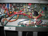
Unfortunately the layout page that SLM sent me is only parts layout, it doesn't show the board traces. I'll post a picture of the power supply region, showing the close proximity of the line out/line in jacks to the diode bridges.
Hi,
The hum in the clean channel on my reverberocket is significant but in no way obnoxious...so it's still a perfect usable amp for any purpose. I have a vintage twin reverb from the 70's and a bassman and several marshalls but I always end playin' the ampeg for gigs and also for recording...so I can live with that hum. (But my marshall superbass and the twin are sooo quiet in comparison...) I'm afraid that hum can get louder as years go by...
That's why it bothers me...I wish I could get rid of that hum so the ampeg will turn almost the perfect amp!
By the way, the power tubes on my ampeg are holding in a different way from the pictures seen above....I bought it new in Andorra (Europe) in 2008 so, maybe is the last version of it...I will post some pictures soon.
In spite of what my wife tells me I do a lot of it.
Anyway.
There are a lot of things that are possible. But by thinking it through most of them can be eliminated.
The R13 and R14 V2-7 junction is the sensitive node.
It is possible that V1 is sensitive. Normally it is turned down by the Volume control, so it "could" have the same noise, but it is reduced by the volume control. However, after I moved the jumper wire that was the main source of trouble with V2-7, even with the Volume on max the hum wasn't much louder or even as bad as it was before the jumper wire move was done on V2. And noise at V1 has 4 stages of amplification vs V2-7 only having 1 stage.
So whatever the source of the noise, if the heater circuit on V2 was wired the same as V1, it wouldn't be any more sensitive than V1 is, which is not very sensitive.
If I plug a shorted phone jack into the send/return just ahead of the phase inverter I get a silent amp. Again whatever is wrong only affect the circuit ahead of that point, V2.
Grounding R13 to C9 junction does not reduce the hum at all. So it is only the second half of V2 that has an issue.
I just tried this, grounding V2b input by shorting out R14 (grid leak). It reduced the hum greatly. Then I tried shorting the line in, and hum was reduced a little bit more. Then I grounded V2a input only, by shorting R10. and that reduced hum somewhat. I think hum is coming in at multiple spots.
If there was a broken trace or a bad part causing that part of the circuit to be more sensitive, then there is no reason that Ampeg would have redesigned the PCB around V2 to match the layout on the PCB around V1. Especially since they were careful to run both sides of the heater voltage all the way to pin 9. This only blocks capacitive coupling by the way. If it was inductive coupling it would not block anything since there is only current in one of the traces. The current to pins 4-5 is already there.
So I think to save time I am going to do this,
1. Just remove the heater jumpers from both V1 and V2.
2. Then using twisted wires I will route the heater wire to pin 9.
3. I will also cut the traces going to pin 9 that run under R13 still, and likewise on V1.
4. I will add the 500 pot between the legs of the heater supply with the center wiper to ground, and disconnect the center tap of the heater winding.
5. Power it up and listen to horrible hum and buzz and noise.
6. Throw the whole thing against the wall.
7. Explain to my wife i need another new amp.
8. Wake up in the hospital... hopefully?
Ha! My thoughts are:
1. take steps (to be determined) to reduce rectifier noise and/or transformer ringing
2. bias up the heaters to +20 or 30v
3. if that doesn't work, tear it all down and rebuild point to point
Here's a pic of the power section of the amp. I've circled and labeled "LV" the low voltage, +/- 15 v supply, and the HV supply. In between those two there are two more diodes, that's the bias supply. At the top, from left to right are jacks: footswitch, line in, line out. Potentiometers: reverb, master, bass, mid.

Attachments
- Home
- Live Sound
- Instruments and Amps
- Ampeg Reverberocket vs hum