Just got an amp(1000w 4 channel lanzar) and a box with a couple eights. Got a big amp so I would not have to stress it and I could tuck it under my seat without it getting hot. I am not trying to thump or anything but if a good song comes on and I'm on the highway with windows down, I want to hear it.
The prob: I have the four channels bridged into two and channels 1&2 keep going into protection mode.
- I can play channel 3&4 all day long as loud as poss. but when 1&2 is going it will cut out.
- I also switched speakers to make sure that was not the problem - It's not.
It must be the amp I will try to post the pic of the board - it looks funky - Please tell me what the deal is, has it been messed with or is that factory? Also what is the resin glue stuff on the board?
Finally, is there a way to reinforce the bridge connection on the board - I can solder - learning is fun so help where you can
http://home.comcast.net/~evan_kristina/pic.html
The brown goo around the solder joints looks like a noob soldered it together without cleaning, but it could very easily (unfortunately) be a factory job. Get yourself some isopropyl alcohol and it should clean it right off... make sure it's as pure as possible. The 70% stuff at the drug store may not cut it.
Thanks - I scrapped off the gue like a dentist, it looks much better but it did not help. Channel 1 is the one that is blown. I hooked up ch 2 and it was good. I hooked up one of the 8's with channel 2 and turnded the settings way up - then hooked ch 3/4 to other with settings all the way down. sounds ok I guess. Your guys help is appreciated but if you know of a way to fix ch1 that would be great.
Is there a way to safely trace ch 1 to find the problem with a meter
thnaks
Is there a way to safely trace ch 1 to find the problem with a meter
thnaks
sss said:
"check the power transistors with a multimeter"
I would like to do this but was wondering how without opening it up while it was still hooked up to the car. what could I power the amp with inside the house? or if you do it while still hooked up in the car, is this safe?
"check the power transistors with a multimeter"
I would like to do this but was wondering how without opening it up while it was still hooked up to the car. what could I power the amp with inside the house? or if you do it while still hooked up in the car, is this safe?
")
Wow - did not know there was a batt inside.
OK I went to a site here[http://www.multimeterwarehouse.com/usingamultimeter.htm[/URL]
have a better idea how to use the multimeter.
Now I have to go and pull the amp from under the seat (for the 6th time) and see what I find.
Also, I bet that there a million amps out there that have the same problem - I will try to post some pics so that others can learn to fix theirs too. If I ever get this one fixed
Again - thanks sss for help
I would do it like this:
Get the multimeter to a short circuit detection mode, I think this is easy. Then, if you know which transistors are for ch1, check if there is a short circuit between any pins at each transistor. If so, get that one out of the board - ulsolder it, then replace it with the same type. If you do not know which transistor is for which channel, you can chceck them all.
Inside the house you can power the amp from an 12V DC power supply. But if you will test it at high powers, you will have to get a power supply that is sufficient for it. Something like 15-20A current capability should be enough. If you do not have such power supply, you can still get the battery out of your car and use it to supply an amp inside your house.
I hope this will help you.
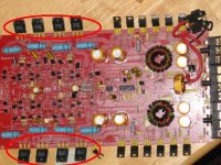
i've marked the trannies u need to check , dont touch the other transistors , those are power supply mosfets
looking at your multimeter i cant tell if it includes an ohmmeter or a short circuit meter ,if u dont know then make a bigger bic of it and i'll tell u .
now dont u try to power the amp when no heat sink attached !
looking at your multimeter i cant tell if it includes an ohmmeter or a short circuit meter ,if u dont know then make a bigger bic of it and i'll tell u .
now dont u try to power the amp when no heat sink attached !
Attachments
1. Rather than taking the battery out of the car, I take the board to the car and hook up to the power supply.
2. I put the meter into detection mode (if has it ) and check the trannies(says sss) or transisters (says disney)
3. then just fix what is short or broken
questions - not sure bout hooking up power to board. Just hook up the power conection for amp, ground or no ground?
also I have opened that pos amp ten times now. Will need your guys help to fix it, but if you think that this is to much for nubie than say it now before I have to open that thing again.
ok ok - No power. Did you look at the close up of the meter to see if it able to detect the short.(last post) If it is, then please explain how to check. thanks again
update - now both channel 1 & 2 are blown, they both go into protected mode at volume low. may be because I have opened and closed the amp ten times now - I may have knocked something lose. Most likely, ch 2 was on it's way out anyway. Still ch 3 & 4 are working fine. I need more POWER- Please advise
update - now both channel 1 & 2 are blown, they both go into protected mode at volume low. may be because I have opened and closed the amp ten times now - I may have knocked something lose. Most likely, ch 2 was on it's way out anyway. Still ch 3 & 4 are working fine. I need more POWER- Please advise
the metter can test resistance , not good enough but thats all u got . put it on x10 (on the pic its on x1k) now when u touch the both wires of the meter it shoul read 0 ohms , if u not touching anything the niddle shoud be on the other end .
now u can check the transistors , touch 2 of the leads if it shows 0 ohm the transistor is dead
every transistor u check 3 times :
lead #1 and 2
lead #2 and 3
lead #3 and 1
now u can check the transistors , touch 2 of the leads if it shows 0 ohm the transistor is dead
every transistor u check 3 times :
lead #1 and 2
lead #2 and 3
lead #3 and 1
before I open it again I just am wondering - Channel 1 & 2 will give you power from the channels when volume is low. When the vol turned up the protection mode comes on - meaning there is a short not that anything is dead. Right?
And - why I assumed that it would have to be powered is because the short only happenes when the power is past a certian level. If the transisters were dead than I could find them with no power - but they are not dead just screwed up.
So- my meter will show that power is flowing through the transisters and not be that helpfull.
It seams that I need the short cicut detector to find the prob, NO?
Again I am new to all this but does any of this make sense?
- Status
- This old topic is closed. If you want to reopen this topic, contact a moderator using the "Report Post" button.
- Home
- General Interest
- Car Audio
- amp repair - help