View attachment 946563
Hi and thanks for reading. I have built this amplifier, please see attached circuit diagram. It is working fine the midrange and treble are good but whenever the amplifier tries to reproduce a low bass note i get a lot of distortion.
What do you think is wrong can you please advise.
Hi and thanks for reading. I have built this amplifier, please see attached circuit diagram. It is working fine the midrange and treble are good but whenever the amplifier tries to reproduce a low bass note i get a lot of distortion.
What do you think is wrong can you please advise.
Attachments
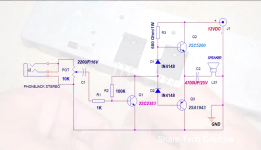

The circuit is wrong: the lower output transistor has no bias. The top transistor is not receiving enough voltage (needs a bootstrap), so distortion occurs. There is no correct NFB from the amplifier output.
Last edited:

Thanks for the replies, much appreciated.
I have checked the diodes and they are as the circuit diagram states. The amp does work with the diodes.
Is there anyway to salvage this project. Can you please make changes or addition of components on the circuit diagram i included.
I have checked the diodes and they are as the circuit diagram states. The amp does work with the diodes.
Is there anyway to salvage this project. Can you please make changes or addition of components on the circuit diagram i included.

Thanks!
What i mean is there anything that can be done to my amp to get it working. Please, not alternative designs.
It is a cheap and cheerful project with a bass disortion problem, not intrested in negative feedback or trying to make it a high quality amplifier. Just want it be stable and make sound.
Many thanks.
This is usually the hardest part. Especially if it is assembled according to the wrong scheme and is not configured 🙂
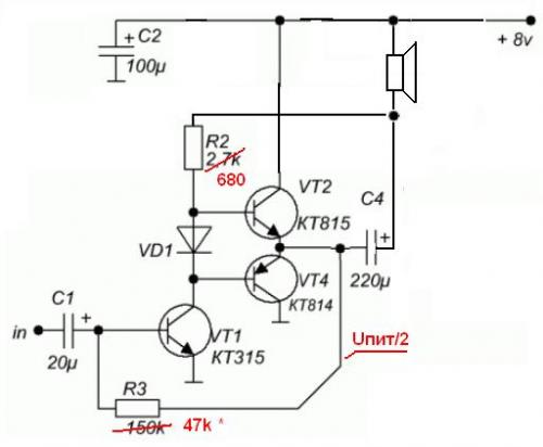
R2 forms nfb for dc and ac voltage. The value is selected when setting 1/2 VDC at the junction point of the emitters Q2 and Q3. Remove D2 (replace with a jumper). Connect D1 and D2 in series as shown # 2 or # 4 (reverse polarity). R3 can be reduced to 100-330 ohms.
Simple circuits require more attention to detail and more complex customization🙂
Last edited:
So move D2 into the same position as D1.
In the circuit diagram i provided the diodes directional arrow is pointed upwards, so in your version i should have the two diodes pointing downwards, is that correct.
Many thanks
In the circuit diagram i provided the diodes directional arrow is pointed upwards, so in your version i should have the two diodes pointing downwards, is that correct.
Many thanks
Just a little confused, you said to compare it against #4. In #4 there is a circuit board trace / track between the two diodes with C3 on the left and the transistors on the right.
On my amp, with the modification applied that you mentioned, there is no track between the diodes. Why the need for two diodes when one should do, or am i missing something.
On my amp, with the modification applied that you mentioned, there is no track between the diodes. Why the need for two diodes when one should do, or am i missing something.
Two diodes connected in series (one after the other) are needed to bias two transitions of the output transistors.
The diagram shows the connections of the parts.
The diagram shows the connections of the parts.
Thanks!
The diode mod has cleared the sound up considerably.
When i dropped R3 from 680 ohms to 100 ohms the volume went down, had to turn the preamp up to get the same loudness, do you know why that happened.
The diode mod has cleared the sound up considerably.
When i dropped R3 from 680 ohms to 100 ohms the volume went down, had to turn the preamp up to get the same loudness, do you know why that happened.
Yes, R3 sets the voltage gain of the first stage which is, roughly speaking, a transconductance stage - the input voltage is converted to a current, the resistor multiplies the current to produce a voltage, smaller resistor -> smaller voltage.
Ideally that resistor would be replaced by a current source to greatly increase the
gain, allowing negative feedback to then be employed to linearize the whole amp.
Ideally that resistor would be replaced by a current source to greatly increase the
gain, allowing negative feedback to then be employed to linearize the whole amp.
Please forgive my amateruish point of view, why is a smaller resistor R3 better.
Also the speaker negative terminal goes to the ground, what do you think of connecting the speaker negative to the +12 positive rail instead.
Do you think the power supply 12v could be raised, and to what value.
The BCE of Q1 should be 6 volts (i.e. Vcc / 2) or the amp may be unbalanced. What do you think of using a capacitor in line with the Q1 drive to block DC and allow the output pair to bias naturally.
Many thanks.
Please forgive my amateruish point of view, why is a smaller resistor R3 better.
Also the speaker negative terminal goes to the ground, what do you think of connecting the speaker negative to the +12 positive rail instead.
Do you think the power supply 12v could be raised, and to what value.
The BCE of Q1 should be 6 volts (i.e. Vcc / 2) or the amp may be unbalanced. What do you think of using a capacitor in line with the Q1 drive to block DC and allow the output pair to bias naturally.
Many thanks.
I think you should get some simulation program on your Computer and then run that circuit in that SIM program..Nothing will burn, nothing will short out and finally you will get lots of knowledge, and eventually a working amp.
You will be able to vary with voltage, with resistance and all what comes with it.. and the best of it, you can see the results without even need to solder anything...
Go for it, it wont get worse, it will get better if you try.
Thanks.
I do very much appreciate the links and am reading everything,
can you please answer the questions i put up as well to make life easier for me and if i misunderstand the tutorials.
I don't have any computer software.
Many thanks
I do very much appreciate the links and am reading everything,
can you please answer the questions i put up as well to make life easier for me and if i misunderstand the tutorials.
I don't have any computer software.
Many thanks
- Home
- Amplifiers
- Solid State
- amp distorting