Hi!
Here is a mod I've made to the excellent Amp Camp Amp by Nelson Pass....
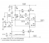
Now it is fully DC coupled (as long as your source is also DC coupled), running on symmetrical supplies. Don't ask for pictures, because it still exists in its ugly
"air wired form".... But: It works perfect, rock stable for two months, DC offset
on the output is around +/- 15 mV, Io (with the values on the schematic) is around 0.8A, and the sound is,..... well, fabulous. I've tried about a dozen similar designs, but this one beats them all - as long as you can live with about 5-6 Watts of output power. I'm running mine from a 200VA toroidal transfo, 2X13V AC, 2x33000 uF filter caps, + a simple darlington based capacitance multiplier filter.
Here is a mod I've made to the excellent Amp Camp Amp by Nelson Pass....
Now it is fully DC coupled (as long as your source is also DC coupled), running on symmetrical supplies. Don't ask for pictures, because it still exists in its ugly
"air wired form".... But: It works perfect, rock stable for two months, DC offset
on the output is around +/- 15 mV, Io (with the values on the schematic) is around 0.8A, and the sound is,..... well, fabulous. I've tried about a dozen similar designs, but this one beats them all - as long as you can live with about 5-6 Watts of output power. I'm running mine from a 200VA toroidal transfo, 2X13V AC, 2x33000 uF filter caps, + a simple darlington based capacitance multiplier filter.
Attachments
Dragonweed,
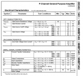
This is great. I don't like to use capacitor coupling with speakers. Can I use 2n5462 in place of 2n5461?
Thanks
This is great. I don't like to use capacitor coupling with speakers. Can I use 2n5462 in place of 2n5461?
Thanks
Also, can I increase supply voltage to +/-15v ? What needs to be changed for this voltage increase?
Well, about the FET-s, as you can see on the datasheet, the three types have different Vgs valuees, as well as different Forward Transfer Conductances. So far I've tried it with only the 5461, but it might work with the 5462 too. Try it, you may have to adjust the value of R9 in order to get it working correctly. The limiting value for max. power supply voltage, is the Vds of the FET-s, which is 40 Volts, so theoretically you can increase power rails to +/- 18-19 Volts, but then the max. dissipation values will increase too, so be careful.
Attachments
Last edited:
Kind of reminds me of NOStalgia. Link: http://www.diyaudio.com/forums/pass-labs/203915-nostalgia-all-fet-jlh-plh-class-amplifier.html
The JFET increases the open loop gain and that will change the distortion profile. Did you measure the gain or distortion? Got any scope photos? I've found it really hard to drive Q1 in this configuration when the output swings close to the rail. I added a PNP emitter follower to drive Q1.
The JFET increases the open loop gain and that will change the distortion profile. Did you measure the gain or distortion? Got any scope photos? I've found it really hard to drive Q1 in this configuration when the output swings close to the rail. I added a PNP emitter follower to drive Q1.
Yes buzz, the way I see it, it is another amp, not a modification to the original topology. Before I say something less than tactful, 😕 I don't really understand the new topology so much. The F.E. went from a common Drain/Source Follower to a common Source. But, there is no Iq current in Q4? Is there? There is a Cap blocking current to ground through the Rs, except when there is signal present, so Q4 must draw current throught he output?
Maybe some explanation would help me out? 😀
Maybe some explanation would help me out? 😀
Yes buzz, the way I see it, it is another amp, not a modification to the original topology. Before I say something less than tactful, 😕 I don't really understand the new topology so much. The F.E. went from a common Drain/Source Follower to a common Source. But, there is no Iq current in Q4? Is there? There is a Cap blocking current to ground through the Rs, except when there is signal present, so Q4 must draw current throught he output?
Maybe some explanation would help me out? 😀
I agree. It is a different amp. Beauty of the ACA is that you basically have very nice SE amp, showing only character of output stage. There is no real advantage to this choice other than higher OLG, allowing more feedback. Didnt really look closely at implementation, but Loadthud is probably right about drive issues. You would probably want pretty high idss input transistor.
I cant say that i understand C1 either. Bootstrapping of some sort. Bypassing the resistor with cap might bemore helpful, as it would increase gain.
Yes, Source current for Q4 comes through the 56 ohm feedback resistor. The voltage drop across that resistor gets hidden by the gate-source voltage of Q4 such that the gate and output are at zero volts. R9 has to be adjusted to null the output.
I like it, but wonder sbout the influence of the input. Ultimately it does give you more gain for feedback,which is important and helpful.

Why no 10K between R5 and R7
I was browsing around and found this amplifier. I'm curious, Why no 10K between R5 and R7? It looks like the gain from Q3 is completely swamped out by the bypass cap. I only browsed ~30 of the 100+ pages of comments trying to see if this has already been answered. I'll look for a "summary site," off to do yard work! 🙄
I like the use of switching supplies for power. A small, damped common mode choke and a small bead on the power results in a very quiet supply. The only problem I've run into with switching supplies is oscillations under certain capacitive loads. This is usually fixable with a zobel (inductor in parallel with a resistor) in the series with the switching supply.
I was browsing around and found this amplifier. I'm curious, Why no 10K between R5 and R7? It looks like the gain from Q3 is completely swamped out by the bypass cap. I only browsed ~30 of the 100+
pages of comments trying to see if this has already been answered. I'll look for a "summary site," off to do yard work! 🙄I like the use of switching supplies for power. A small, damped common mode choke and a small bead on the power results in a very quiet supply. The only problem I've run into with switching supplies is oscillations under certain capacitive loads. This is usually fixable with a zobel (inductor in parallel with a resistor) in the series with the switching supply.
Attachments
you can try it , and certainly expect different THD spectra , comparing to original
maybe you'll like it , maybe not
maybe you'll like it , maybe not
Finally....I've tried the suggested 10kohm resistor mod between R5 and R7, the THD value dropped to almost half, but it effectively killed the "magic" of this amp, the speed, dynamics, and punch present with the original circuit is all gone.... So much about the differences between theory and practice. Nevertheless thanks for your suggestion. (I used a switch to bypass the 10k, so the comparision could be made almost immediately)
C2 is with reason connected to R7,R5 node - to modulate gate of upper mosfet
introducing resistor in between transforms mu-like operation to common CCS , ACA becoming ordinary SE amp
introducing resistor in between transforms mu-like operation to common CCS , ACA becoming ordinary SE amp
Yes, I was aware of that fact from other Pass designs..... now I've replaced the 10k resistor with a pot, so you can "transit" between the two modes. For my ears the truth is somewhere midway of the two ends. The shorted version is a bit too "etched", while the 10k setting is too soft, loosing the dynamic impact in regular SE mode. Thanks again for the suggestion.... if you have any other ideas I am glad to try them, this is not my most "familiar" territory.
Last edited:
It's not a constant current source because the output is tapped between R1 and R3.introducing resistor in between transforms mu-like operation to common CCS , ACA becoming ordinary SE amp
Q3 regulates the voltage drop from the Drain of Q1 to the source of Q2, but when output current flows and thus changes the voltage drop across one of the resistors, Q3 tries to make a compensitory change to Q2's current to maintain the Q1 Drain to Q2 Source voltage. If Q1's current is increasing and going to the output, Q2's current will reduce. If the R1, R2 pair are the same value as the R3, R4 pair, the changes in current will be as close as the resistors dictate. Mu stage operation is preserved.
The problem is that R7 and the new resistor are too high resistance to get any bandwidth out of Q2. Try something like 470 of 1K. See the schematic I posted in the ACA thread, reply #149 Link: http://www.diyaudio.com/forums/pass-labs/215392-amp-camp-amp-aca-8.html#post3095656
I posted that before I fully understood C2's role in modulating Q2's current.
- Status
- Not open for further replies.
- Home
- Amplifiers
- Pass Labs
- Amp Camp Amp Mod