ACA is just use one fet at input , look like is the same aleph (long tair pair at input stage) single end with variable current source .
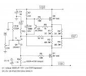
"The problem is that R7 and the new resistor are too high resistance to get any bandwidth out of Q2. Try something like 470 of 1K." Yeah, you were absolutely right... this just skipped my attention. Now i am using 1.5kohms in both positions (instead of the the 10k-s), this gives me a pole of 48 kHz with the Cgs of the IRF 640. (with 10k it was 8.8kHz... 🙁( ). At this point let me tell you, the sound is just incredible (+/- 15v cap. multiplier filtered supply rails, set to1.2A idle current), whoever listened to it couldn't believe the dynamics and naturalness of this 6W little thing. After having tried about a dozen similar SE designs this turned out to be by far the best.
Last edited:
Did you try changing the R1-R3 ratio or the closed loop gain? Those things influence the distortion.
I just ran across this, I missed it previously. Same basic idea for a negative impedance current source.
http://www.diyaudio.com/forums/pass-labs/161716-aleph-current-source-mod.html
http://www.diyaudio.com/forums/pass-labs/161716-aleph-current-source-mod.html
Excellent posts by Wensan. I'm sorry that we have not seen him around lately.
I have been referring to this circuit as a "mu follower" for no better reason than
I like the name.
It has two distinct advantages over the Alephs: It is slightly simpler and it
works better driving low Vgs enhancement and depletion mode transistors.
😎
I have been referring to this circuit as a "mu follower" for no better reason than
I like the name.
It has two distinct advantages over the Alephs: It is slightly simpler and it
works better driving low Vgs enhancement and depletion mode transistors.
😎
I was playing with the R1-R3 values, the "sweet spot" for me is R1=0,28 ohm (2X0,56 parallel) R3=0,34 ohm (2X0,68 parallel). For the gain setting resistors the best result is 56 ohm and 7,5 ohm respectively, also increased the value of C1 to 6600 uF (2x3300uF/10V low ESR bypassed with 2,2uF PP). If you change the value of the series gain setting resistor (56 ohm) keep in mind that it also shifts the working point of the input J-fet, so you must readjust the value of R9 to 0VDC at the output.
When I tried to make my circuit DC coupled on the output, I didn't like the way temperature and mains voltage changes made the output offset drift. I ended up just following the JLH69 with a capacitor on the output, a higher impedance in the feedback network and a smaller C1 with lots of voltage across it.
Nelson, referring to your distortion and feedback article, does the mu-follower or Aleph current source count as "feedback"? Do they cause a raise in higher order distortion products?
Nelson, referring to your distortion and feedback article, does the mu-follower or Aleph current source count as "feedback"? Do they cause a raise in higher order distortion products?
In the past 5 months I checked regularly the Iq and DC offset drift on my DC coupled version. Io changed between 1.18-1.22 A, DC offset drift is no more than +/- 30 mV, under various temperature and AC mains conditions, so for me this never occured as a problem....
ok, thanks 😉, but what kind of power supply?
switching, capacitance multiplier, regulated, unregulated, etc etc..
5000uf, 10000uf, 100000uf the filter el-capacitors?
switching, capacitance multiplier, regulated, unregulated, etc etc..
5000uf, 10000uf, 100000uf the filter el-capacitors?
whatever you choose
I think most iterations are already covered in original article and several threads about ACA
start with most simple for which you get parts at home , then build up
name of the game is to play
I think most iterations are already covered in original article and several threads about ACA
start with most simple for which you get parts at home , then build up
name of the game is to play
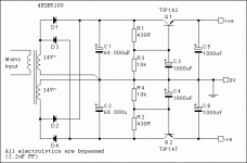
My version is running on a capacitance multiplier (unregulated) supply. The transfo is a 140VA toroid (2x14V 5A), rectifiers are SB5100 Schottkys (5A 100V), filtering is done with 4X33.000uF/25V Nichicons, + 8A Darlington cap multipliers. Raw supply is +/-16V, after the drop on the multipliers is +/- 12V.
Last edited:
I was playing with the R1-R3 values, the "sweet spot" for me is R1=0,28 ohm (2X0,56 parallel) R3=0,34 ohm (2X0,68 parallel). For the gain setting resistors the best result is 56 ohm and 7,5 ohm respectively, also increased the value of C1 to 6600 uF (2x3300uF/10V low ESR bypassed with 2,2uF PP). If you change the value of the series gain setting resistor (56 ohm) keep in mind that it also shifts the working point of the input J-fet, so you must readjust the value of R9 to 0VDC at the output.
Hello, and thanks for sharing the schematic of your amp.
I am also interested to built this amplifier as a significant upgrade to my really nice 5 Watt class A amplifier (3-5 Watt Class-A from redcircuits) that I built before I discover "ACA". Also I found that it sounds better than my class T-Amp, SMSL SA-S1 on my Mordaunt Short MS30i speakers.
Anyway, I would like to ask if you can update your schematic with the tweaked values of the components you've made into the original circuit, to make it sound better, according to you.
Because as I am an amateur and not enough educated in electronics, many of the terms that are being reffered I do not understand them.
So let me start asking if the R9 is a DC-offset adjustment for the output and the values of R2 and R4 remain unchanged in the circuit?
Also If I omit the input DC blocking capacitor, I omit the 100k input resistor too? (Both resistors have asterisks in the schematic diagram).
I was thinking that this 100k can be replaced by 100k log pot as a volume control, but doing this, do I still need the input capacitor? I'm a bit confused about that and I don't want to use too any capacitors for the input or anywhere in the signal path.
Thank you very much for your time and I would appreciated if you could enlighten me, Theologos.
Sorry for the long delay, I was a bit "snowed in" lately.... Here is the latest, updated version, with all the recent values. For my ears this version sounds the best, but depending on your ears and system, your mileage may vary.... As for capacitors, use the best you can get, it pays off (especially C1). For volume pot you can use values from 10k to 100k. As you see this way the whole thing is DC coupled (except the necessary C1 as DC blocker in Q4 source leg), still surprisingly stable -in my amp output DC never shifts more than +/- 30 mV- under any load or temperature conditions.
Attachments
Last edited:
Thank you for posting an updated schematic and also including the pot!
I just have some questions for your updated schematic.
The R1 and R2 seem to raised the values from the original and from your previous post I have quoted.
Did those changes serve you a better sound for your setup?
Also the values of C4 and C5 how much critical are they? You have noted 10-47uf. I have capacitors, of values : 10-22-33-47uf (I suppose they are good quality, as they are brands like Nichicon, Philips, Panasonic).
I also have a pair of 10uf MKP, if is it any good there.
Thank you again!
- Status
- Not open for further replies.
- Home
- Amplifiers
- Pass Labs
- Amp Camp Amp Mod

