The potentiometers were oriented towards the top for easy access in the guide.
That's quite understandable 6L6. You're right of course.
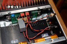
The potentiometers I swapped at the bottom of the amp are easy to adjust, and they don't need often adjusting. A small screwdriver from the top is simple to adjust those lower potentiometers.
My opinion it is better to have the hot resistors above the rest of the caps etc.
My opinion it is better to have the hot resistors above the rest of the caps etc.
I built my amp camp amps in September and I was immediately struck with the lively & very musical character of these amps. However, there were a few things that did not quite suit my system so I started playing with the design in spice but I thought that the overall lovely character of the sound was worth experimenting with.
I found that the high output impedance did not give the bass control I was used to so after more experimentation in spice I found that making R1 & R2 0 ohms and moving those resistors to add to the resistance of R3 & R4 gave a much lower o/p impedance. In spice I could find no drawbacks to this and in real life it sounds just fine.
I do not use preamps so for my system with 2 way 89db / W /M transmission line speakers I needed a little more closed loop gain. After a lot of model testing in spice I found the IPP600N25N3 and this gave enough extra open loop gain to make a CLG of 10 or 12 possible.
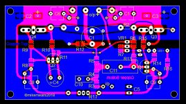
So I made some new prototype PCBs to accommodate the TO220 IPP600N25N3s and with these two mods combined I can get an o/p Z of about 0.13R which when combined with the crossover series impedance gives an overall damping factor of about 20 which is quite reasonable with my 8" drivers.
The prototype boards were also designed for SM resistors so I could use the excellent Susumu RG2012 resistors throughout ( except for the WW power resistors ) Also I added the option for an input filter & snubberized bypass caps for the rails.
These boards are now up & running & the sound is quite astonishing - more detailed than the original ACAs ( actually more detailed than any amp I have every heard ! ) but still very musical and engaging.
For me this is still very much a work in progress situation - there are many options that I want to try including dual rails, balanced working, no o/p capacitors, trying o/p chokes etc etc . . .
But for the time being I have a new planned PCB that has the flexibility to give all of the above options.
I would be interested to see / hear what other options others are considering.
For now I add the circuit I am listening to at present & my proposed new PCB as is at present. ( I just used what models were there in LT spice so the i/p jfet is different and I do not show any caps in spice )
I found that the high output impedance did not give the bass control I was used to so after more experimentation in spice I found that making R1 & R2 0 ohms and moving those resistors to add to the resistance of R3 & R4 gave a much lower o/p impedance. In spice I could find no drawbacks to this and in real life it sounds just fine.
I do not use preamps so for my system with 2 way 89db / W /M transmission line speakers I needed a little more closed loop gain. After a lot of model testing in spice I found the IPP600N25N3 and this gave enough extra open loop gain to make a CLG of 10 or 12 possible.
So I made some new prototype PCBs to accommodate the TO220 IPP600N25N3s and with these two mods combined I can get an o/p Z of about 0.13R which when combined with the crossover series impedance gives an overall damping factor of about 20 which is quite reasonable with my 8" drivers.
The prototype boards were also designed for SM resistors so I could use the excellent Susumu RG2012 resistors throughout ( except for the WW power resistors ) Also I added the option for an input filter & snubberized bypass caps for the rails.
These boards are now up & running & the sound is quite astonishing - more detailed than the original ACAs ( actually more detailed than any amp I have every heard ! ) but still very musical and engaging.
For me this is still very much a work in progress situation - there are many options that I want to try including dual rails, balanced working, no o/p capacitors, trying o/p chokes etc etc . . .
But for the time being I have a new planned PCB that has the flexibility to give all of the above options.
I would be interested to see / hear what other options others are considering.
For now I add the circuit I am listening to at present & my proposed new PCB as is at present. ( I just used what models were there in LT spice so the i/p jfet is different and I do not show any caps in spice )
Attachments
Last edited:
Hi Mike, seems you found something special in the IPP600N25N3. However, there are 2 things I noted after replacing the Jfet with 2SK170 and run the simulation :... These boards are now up & running & the sound is quite astonishing - more detailed than the original ACAs ...
1. There is a slight stability issue at 2MHz, easily countered by changing R15 to 680 ohm.
2. Unlike the original ACA, connecting output directly from source of M3 change phase of second harmonic to become positive. This could be one factor that contributes to perception of detail. You may want to listen to both normal and reverse speaker polarity connection to choose one that works best for you.
Hi Indra,
IPP600N25N3 is not special but I think well suited to this task.
It has quite good linearity at around 2 amps & higher transconductance than IRFP240
In reality the amps show no signs of instability on the scope
You have private message
mike
IPP600N25N3 is not special but I think well suited to this task.
It has quite good linearity at around 2 amps & higher transconductance than IRFP240
In reality the amps show no signs of instability on the scope
You have private message
mike
There is a slight peak at ~2Mhz visible on AC analysis.... You have private message...
Your mailbox is full, so I post the model here.
.MODEL 2SJ74 PJF(Beta=38m Rs=7.748 Rd=7.748 Betatce=-.5 Lambda=4.464m +Vto=-.28 Vtotc=-2.5m Cgd=85.67p M=.3246 Pb=.3905 Fc=.5 Cgs=78.27p Isr=129.8p +Nr=2 Is=12.98p N=1 Xti=3 Alpha=10u Vk=100 Kf=26.64E-18 Af=1)
.MODEL 2SK170 NJF(Beta=34m Rs=4.151 Rd=4.151 Betatce=-.5 Lambda=1.923m +Vto=-.39 Vtotc=-2.5m Cgd=20p M=.3805 Pb=.4746 Fc=.5 Cgs=25.48p Isr=84.77p +Nr=2 Is=8.477p N=1 Xti=3 Alpha=10u Vk=100 Kf=111.3E-18 Af=1)
There is a slight peak at ~2Mhz visible on AC analysis.
Your mailbox is full, so I post the model here.
Thx 🙂
Interesting - I had a look with the new model in spice and saw that the little raising you noticed at 2meg equated to some overshoot ( but no ringing ) that I had noticed on square waves.
The overshoot in spice is more pronounced that in reality - but is still there.
I don't think this will impact much to the detriment of the sound in the way they ringing would but will check this out - thx for spotting it.
It's interesting that increasing the gate stopper on M3 helped this, but increasing the same on M4 made it worse !
I think in reality increasing M3 gate stopper to 200 ohms ( & possibly reducing M4 GS to 50 ohms ) will fix it
mike
Is this the Meanwell adapter for ACA (24V / 5A)?
GST120A24-R7B MEAN WELL USA Inc. | Power Supplies - External/Internal (Off-Board) | DigiKey
GST120A24-R7B MEAN WELL USA Inc. | Power Supplies - External/Internal (Off-Board) | DigiKey
Is basically the same but can can see the plug is different. The one supplied is GST120A24-P1M
OK......thank you. The standard plug instead of the DIN type.
Here it is:
GST120A24-P1M MEAN WELL USA Inc. | Power Supplies - External/Internal (Off-Board) | DigiKey
Anyone think the ACA would work as a headphone amp?
After all, once you have high impedance headphones, the power will 'drop' to a more appropriate level.
Any disqualified here?
After all, once you have high impedance headphones, the power will 'drop' to a more appropriate level.
Any disqualified here?
As far as I remember it has been discussed and the conclusion was that it works fine. I have an adapter which converts banana to headphone stereo plug but has not tried it with ACA yet. This adapter loads the output with 8 ohm (made for tube amp) and then it has a voltage divider parallel with the 8 ohm resistor to reduce the output a bit. This should not be necessary. But may ensure that the headphone will not melt caused by an error. Maybe some ear protection also.
I would be very interested to find out if the IPP600N25N3 is in fact reliable in this respect or not because it does appear to have a performance advantage which I think will contribute to the good sound.
So far the amps with these devices have been running without any problems for about 12 hours a day for 3 days. Does anyone know if there are specific parameters that would suggest their reliability or tests that can be done or does one just wait for disaster to strike ?
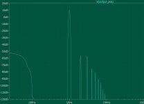
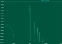
I have attached images of the FFT in LT spice comparing IRFP240 & IPP600N25N3.
Hugh Dean has commented that he thinks that the fast decline in HD from 2nd to 3rd to 4th to 5th etc is a good indicator of a good sounding amp. So far in my testing the IPP600N25N3 is way out in front of any other device I have simulated in this respect - Not so interesting if it's just about ready to self destruct but possibly very interesting if it isn't ?
mike
Attachments
Anyone think the ACA would work as a headphone amp?
After all, once you have high impedance headphones, the power will 'drop' to a more appropriate level.
Any disqualified here?
I have been using ACA as headphone amp for years. I do use two resistors on the output to bring the level down, just like you would on tube amp. The headphone jack and resistors are in small separate box with just two wires going to ACA speakers output. I switched the live and ground though.
Sound is heavenly.
Pictures of your diy Pass amplifier
Yes, I think the IPP600 is special in the ACA, but you are right at the frontier there. To avoid fatal problems, usual prevention steps are :I would be very interested to find out if the IPP600N25N3 is in fact reliable in this respect or not because it does appear to have a performance advantage which I think will contribute to the good sound....
1. use appropriate gate stopper resistor, in your case I think should be at least 680 for R15, M3 should be more stable due to R10 shunting from drain to gate.
2. operate at reasonable temperature
3. use RC shunt as per Paul Bysouth on M4 if the above steps are deemed insufficient
But there is also a chance that the IPP600 is inherently stable as is.
There is also other options such as a CFP gain stage that I try in simulation attached that also needs >820 ohm gate resistor R3 to counter a peak at ~2MHz. However, mosfets used are regulars of Pass Labs production, no unexpected nasties.
Attachments
Last edited:
I have the 2SJ28 (original) and am thinking of using that in a “P-fet” ACA.
What are your thoughts?
Forgetaboutut?
The schema needs to be turned around a bit of course, all devices reverse polarity and I need the P-version of the IRF240, being IRF9240 (i have something similar I think, in TO-3).
And I specially need that extra bias for the 2SJ28. Something that is referenced positive.
It would surprise me if I am the first to try this. . . Any thoughts?
Albert
- Home
- Amplifiers
- Pass Labs
- Amp Camp Amp - ACA