ACA problem update:
I know I should have tried each in sequence, but these 3 changes in concert solved my distortion problems:
1. Reflowed a few solder joints on ACA pcb.
2. Finished the Korg B1 and inserted into system
3. Changed a cheap rca cable.
I'm guessing the preamp was the culprit, but nice music is now flowing, and I'm not inclined to screw around any more.
Thanks to numerous folks who chipped in their advice, but in particular Alan and Thomas who were the first to come to my rescue.
Cheers
Craig in Seattle
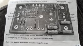
All these measurements were correct on my pcb. Have 4 pcb all with same problem sound output is at a low level and fades in and out no switch on thump so i think its the output stage not working. Any advice would be great.cheershttps://www.diyaudio.com/forums/attachment.php?attachmentid=892249&stc=1&d=1605102247
Attachments
Last edited:
What power supply are you using? Test each amp separately in stereo mode. The turn on thump should be present until used in bridged mode. It’s a power hungry little beast. The DIY Audio supplied brick does a great job. I made my own ultra linear power supply later on with boards from eBay and huge shielded toroidal transformer from Toroidy and both amp and power supply run very warm. I suspect if every thing measures OK your not getting enough juice!
Hi Brian, Did you see my response to the same question on the Amp Camp Amp Kit 1.6/1.8 thread post #918?
Hi Brian,
Umm, not getting warm is odd.
Do the leds 'pulse' on and off with the 'sound output'?
Could you set the 'bias' voltage to 12 volts?
Have you checked the voltages as per the troubleshooting section of the build guide?
Have you got the transistors in the right places and the right way round? Have you got the capacitors in the right way round?
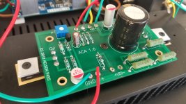
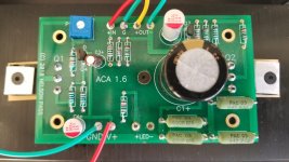
Best post some good pictures of your build.
Alan
hi steve the power supply is ok its switched mode 24v am getting all the right readings to the output transistors but they are stone cold?
I don't think your readings can be right if the outputs are cold.
The midpoint (12v) can still be correct when there are other issues. Measuring from ground can you tell us what voltage you have on each of the 100 ohm 'gate' resistors.
You should see approximately 16 to 17 volts on the upper one and around 5 volts on the lower. The difference between the two readings (in other words the voltage between those two resistors) determines how hard the output transistors conduct. If that voltage is lower than around 11 volts then the outputs will not be drawing sufficient current.
If that is the case then you need to check around Q3 but lets see what you've got first.
Two quick questions.
1/ Is the bias preset around its midpoint (set in the middle) in order to get the 12 volts midpoint or is it 'one ended'?
2/ Could there be any doubts over issues with the semiconductors? Were they from a reputable source or supplied with the kit?
It is odd for all four of your boards to be the same.
Very strange then. I think we can discount the 2SK simply because the midpoint voltage adjusts OK.
I'll have to keep thinking") Nothing suggests itself at the moment to the circuit setting up correctly (the 12 volts) and yet you only seeing 3.2 volts on the lower FET gate.
Nothing suggests itself at the moment to the circuit setting up correctly (the 12 volts) and yet you only seeing 3.2 volts on the lower FET gate.
This is the voltage that just doesn't compute. The lower FET being off should be giving you a high midpoint voltage... and it is not.
The 12 volts you see on both B and E of Q3 show that no voltage is being developed across the low value resistors on the output... exactly what the lower FET being off would do.
One more check to be going on with.
There should be zero (really zero) voltage across both 100 ohm gate resistors. That is worth checking.
I'll have to keep thinking
Nothing suggests itself at the moment to the circuit setting up correctly (the 12 volts) and yet you only seeing 3.2 volts on the lower FET gate. This is the voltage that just doesn't compute. The lower FET being off should be giving you a high midpoint voltage... and it is not.
The 12 volts you see on both B and E of Q3 show that no voltage is being developed across the low value resistors on the output... exactly what the lower FET being off would do.
One more check to be going on with.
There should be zero (really zero) voltage across both 100 ohm gate resistors. That is worth checking.
One remote scenario that could just about do this (and it would be a 100 to 1 chance) is that either C2 which is the 1000uF across Q3 is leaky (fitted with wrong polarity perhaps) or that there is some bizarre issue with Q3 such as it not being what it is supposed to be (for example a PNP fitted instead of an NPN or perhaps something with none standard pinouts).
- Home
- Amplifiers
- Pass Labs
- Amp Camp Amp - ACA