When I test resistance with my canadian tire meter, I have over 8mil ohm one direction and 10-14mil the other. None of them seem to be exactly the same. I just tried my fluke meter and everything is OL on it... So I guess its back to installing to card. I have to put one transistor in each bank to see the wave form properly right?
I'm not 100% sure but I think the amp will oscillate with one high-side and one low-side FET for any one of the driver ICs. This is not a definitive test, however, because the light loading will not show what will happen when the IC is fully loaded.
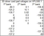
I was going to install the card but decided I better recheck the pads for proper voltages. Now I have 4 readings that are only -80ish volts and they fluctuate -78.x to -81.x vdc.
I don't think that is normal. When the card was in I'm pretty sure I had much higher voltages there. Thats were I got the reading from before. Unless something happened before I removed the card again and found the 2 shorted transistors. Its the first time I've ever had 2 perfectly new transistors I just installed short all 3 legs.
Here is a pic of the current voltages on the output card pads. I sure don't wanna install the card if there is something with those -80volt pads.
Attachments
Isn't pin 2 of those ICs directly connected to the pins that had 80v on them?
Isn't pin 5 connected to the negative rail?
Isn't pin 5 connected to the negative rail?
I'll have to do some tracing for you... but your likely right. I will find out and get back to you. 🙂 I checked 2 IC's on the same side of the card and both had the same reading. I'll go trace the paths.
Hi Perry,
Sorry, I had some other ones to finish up. Yes, you are correct. All pin 2 on all 4 IC's connected to the pads that had 80volts on them. and yes pin 5 of each pair connect to neg rail.
Sorry, I had some other ones to finish up. Yes, you are correct. All pin 2 on all 4 IC's connected to the pads that had 80volts on them. and yes pin 5 of each pair connect to neg rail.
How do you get 5.18v DC between the pins that connect to points with more than 50v difference between them?
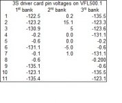
With the card installed I have these readings currently (please see pic). The -80volts are back up. rrrrr down I guess.
I installed 1 high and 1 low output per IC. Gave it power threw a current limiter, power on no protect, switched it over to fused power as soon as the relays clicked on to release muting the amp started making a clicking sound from an inductor, after about 5 seconds POW!. The low side fet from U5 blew explosively.
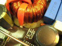
The inductor that seems to be making the noise is in that section. It also seems to have one really dark strand on it (can sort of see from pic).... is there a way to test it?
I'll remove the outputs from that IC and see what voltages I have again on those pins
I installed 1 high and 1 low output per IC. Gave it power threw a current limiter, power on no protect, switched it over to fused power as soon as the relays clicked on to release muting the amp started making a clicking sound from an inductor, after about 5 seconds POW!. The low side fet from U5 blew explosively.
The inductor that seems to be making the noise is in that section. It also seems to have one really dark strand on it (can sort of see from pic).... is there a way to test it?
I'll remove the outputs from that IC and see what voltages I have again on those pins
Attachments

Last edited:
It's almost certainly shorted. Generally, to test an inductor, you either need an inductance meter and the value of the inductor or an inductor/transformer ringer.
Crappy deal... How close to exact would a replacement need to be? Need same model/board series/manufacturer orrrr ???? Is she done for??
Soooo.... I just uncoil the wire, measure it and count the strands and make a new one?? Sounds like fun. lol Never done it before... where can I purchase the wire?
When I remove the inductor, should the other sections of the amp operate properly afterward? Or would not having it installed cause an issue?
Don't do anything with the inductor until you read section 11 on the Tech Tips 7 page of the tutorial.
I don't think that the missing inductor will prevent the amp from functioning.
I don't think that the missing inductor will prevent the amp from functioning.
Read it over before, read it again this weekend, and going to read it over again tomorrow while doing the work... thanks Perry, your tutorial really is SO valuable and a great guide. 🙂
I'll get the material ordered up and see how it goes.
I'll get the material ordered up and see how it goes.
- Status
- Not open for further replies.
- Home
- General Interest
- Car Audio
- American Bass VFL 500.1