
Back to this amp.
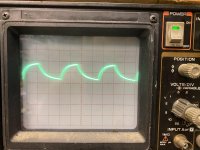
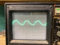
I get bad drive signals on all 6 banks of fets .
The trace was aligned on the center line before taking any readings and the scope is set to 10us 5 volts/div
Any thoughts ?
I get bad drive signals on all 6 banks of fets .
The trace was aligned on the center line before taking any readings and the scope is set to 10us 5 volts/div
Any thoughts ?
Attachments
-
 612D09E5-F594-4B9F-AC57-1E2DB8BB2860.jpg978.7 KB · Views: 90
 -
 C6C89498-70BE-4EAD-84CC-18696ECFE892.jpg956.8 KB · Views: 83
 -
 887FB788-25B1-439A-B95D-1DE2984068E1.jpg964.5 KB · Views: 100
 -
 DEAF096C-E285-4424-83FC-B707FA74BBDC.jpg982.7 KB · Views: 82
 -
 79AAC27F-9124-472D-A873-7FF7CCA91A0C.jpg985.9 KB · Views: 60
 -
 5D24AB04-1F6C-4613-9D95-9628EE36C6DC.jpg989.3 KB · Views: 56
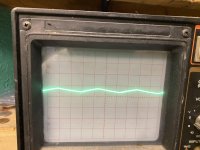
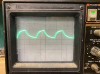
That's about what you'd expect with a loading cap except the second one. Check the drivers and the signals/voltages on them.
Bank 2 is the one with bad drivers signal . The drive looks good at the drivers but when it gets to the fet it has no drive .
Bank 2 is the bank that the diode was broken and I replaced it with a 1N4148
Bank 2 is the bank that the diode was broken and I replaced it with a 1N4148
The circuit is simple. It can't have more than about 5 or 6 components.
Did you load other locations on that driver circuit?
Did you load other locations on that driver circuit?
A couple of drivers are defective .
The original drivers were A1275 and C3228
Instead of using the BD139/140 as replacements since I have to use double sided tape on a few of them so the back doesn’t short to the buss bars in the amp .
I’m wondering if I can replace them with the following
https://www.mouser.com/ProductDetai...hild/KSC2383OTA?qs=ljbEvF4DwOMLawNvPc%2Bttw==
https://www.mouser.com/ProductDetai...rchild/KSA1013YBU?qs=ljbEvF4DwOOSxXIRPq9yUw==
Last edited:
Ok I replaced all of the drivers again and redid the solder connections on the resistors and 10 volt diodes .
All waveforms are identical now .
I had issues with 1 bank of fets before replacing the drivers since that 1 bank of fets had no drive on it would it affect the rest of the banks as well since all the power supply fets were heating up
All waveforms are identical now .
I had issues with 1 bank of fets before replacing the drivers since that 1 bank of fets had no drive on it would it affect the rest of the banks as well since all the power supply fets were heating up
There are 6 banks of fets in this amp . Along with 6 transformers and 6 banks of driver transistors .
Can I put 2 in each bank to test or would that be a lot of load on only 2 fets per bank for testing
Can I put 2 in each bank to test or would that be a lot of load on only 2 fets per bank for testing
There are two banks per transformer. One bank drives the primary to ground then it switches off while the other bank does the same.
You can install only one FET per bank (2 FETs per transformer).
You can install only one FET per bank (2 FETs per transformer).
Power supply is working correctly now with 1 fet per bank .
Not sure why when I replace the drivers I always have issues the first time around
Not sure why when I replace the drivers I always have issues the first time around
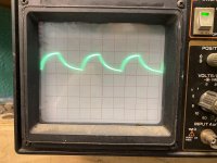
With all of the fets installed and the power supply board disconnected from the output board .
The fets still get warm and continue to heat out of the heatsink at idle . Not sure for his is normal or if I still have an issue .
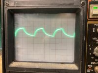
Here is what I get on all of the banks of fets .
Scope set to 10us 5 volts/div
The fets still get warm and continue to heat out of the heatsink at idle . Not sure for his is normal or if I still have an issue .
Here is what I get on all of the banks of fets .
Scope set to 10us 5 volts/div
Attachments

What's the drive look like on the other side of the gate resistor?
What value gate resistors are you using?
What FET?
What value gate resistors are you using?
What FET?
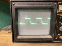
I'm assuming that the trace wasn't aligned to the reference line.
Try changing the gate resistors to 22 ohms for the 2 FETs on one transformer. Do the FETs run cool?
How long does it take the FETs with the 47 ohm resistors take to heat up too hot to touch?
Try changing the gate resistors to 22 ohms for the 2 FETs on one transformer. Do the FETs run cool?
How long does it take the FETs with the 47 ohm resistors take to heat up too hot to touch?
It takes around 3 mins to get to hot to touch .
I replaced 2 gate resistors for 1 transformer to 22 ohm gate resistors those 2 remain cold the other 4 in that bank with 47 ohm resistors heat up
I replaced 2 gate resistors for 1 transformer to 22 ohm gate resistors those 2 remain cold the other 4 in that bank with 47 ohm resistors heat up
Last edited:
3 minutes to heat up isn't awful and could be normal.
That said, for all of the diagrams I have that use the 1405, all but one uses the 22 ohm gate resistors.
Replace all of the gate resistors for that transformer with 22 ohm, install all of the FETs for that transformer and confirm that they still run cool. If they heat up slightly more, install of the FETs for a transformer with 47 ohm resistors and see how much quicker they get hot.
- Home
- General Interest
- Car Audio
- American Bass VFL-1100.1