It's been 3 or 4 years since this newbie started learning tubes from the wealth of knowledge here. In that time I've been collecting schematics, studying, experimenting, buying parts and tubes that mostly just sit, fun to me but weird to my wife. A few months ago I fell into starting something ambitious, figuring out how I would go about building a direct bias 300B PSE amp with dual PSU's. Inspired by Andrea Ciuffoli, because I kept coming back to his 300B PSE schematic over time. I began with his schematic and dumped every thought I'd need to remember about making one myself onto paper. Simultaneously I've wanted to make dual "boat anchor" PSU's for it, inspired by the Border Patrol amp I really liked at AXPONA. The intention is for the boat anchors to have variable B+, umbilical connected to the amp, so I can re-use the PSU's maybe for a second project. So I'm imitating Andrea Ciuffoli and Border Patrol here but learning. I've attached the schematic as of today, if anyone wants to comment, recommend, help, find errors, etc. Along with the electronics, I'm also doing the mechanical design in 3D CAD as I hope to machine and fabricate the chassis all myself as well. As that gets farther along I'll post 3D models too. Thanks!
Last schematic update: See most recent "last update" post from me.
Last schematic update: See most recent "last update" post from me.
Attachments
Last edited:

Are you sure that LL1660 AltT is the best interstage for 5842?
In this operating point the tube's Ri about 2k.
Alt T primary inductance only 33H.
This has at 20Hz 4147R impedance.
The LF frequency behaviour would be weak and distortion ramping.
Alt S provides 130H at 10mA current.
If you change R15 to 200R and R8 to 22k, the tube at -about- 145, 10mA, -2V operating point will drive 300B grid up to A1 (below 2V peek input voltage).
Thank you for this info. The original schematic is Cioffoli unchanged. I like it! My main source is XLR from a DAC and the Jensen steps up more. So less gain in the Lundahl is better considering the improved inductance. My goal is to modularize that driver board to a standard mounting hole spacing, so I can swap out driver boards over time and try other tubes besides 5842. The independent PSU's per channel would even allow me to install different driver boards in each channel to do A/B fast comparison. My goal anyway.
Very cool! Will be watching with great interest 🙂
What software did you use to make this document? Very clean and professional.
What software did you use to make this document? Very clean and professional.
If you want to operate it with replaceable driver module, can be considered to use another (lower output impedance, even higher gain -step up transformers always struggling with challenges-) tube, another IT (IMO this Lundhal -even the amorphous one- pretty mediocre), or completely different design (for example trioded high gm pentode).
I would put to "module" the IT and the stage HT power section too, because so whole architecture would be interchangeable.
p.s.
For example in US, Dave Slagle - Intact Audio - make super 1:1 IT. Not cheap, but worth it. With high gm tube it's appropriate solution.
I would put to "module" the IT and the stage HT power section too, because so whole architecture would be interchangeable.
p.s.
For example in US, Dave Slagle - Intact Audio - make super 1:1 IT. Not cheap, but worth it. With high gm tube it's appropriate solution.
Very cool! Will be watching with great interest 🙂
What software did you use to make this document? Very clean and professional.
It's just Microsoft Visio. I've collected many electronics shape stencils when I started the hobby. I can zip them up if people DM me for them. Visio also comes with electronics stencils, and you can find free ones.
If you want to operate it with replaceable driver module, can be considered to use another (lower output impedance, even...
I appreciate your interest and help. I expected struggles in driver stage design and IT that's why I'm going modular PCB with that aspect. The power tubes are point to point but with turret panels. The IT is mounted in chassis but I suppose I should give it more space so I can fit and try other IT's. I hope to "try out" different driver tubes, 6S45P was also on my list. Maybe even try a CCS in place of the anode resistor on the driver board. My hope is that it becomes my "platform" to experiment heavily with the driver stage until it's best without having to tear apart point to point drivers every time.
Last schematic update:
2025/05/19: Input selector was leaving T1 secondary floating, improved switching with 4P3T switch to not allow T1 to ever "float" regardless of what input is selected. Bypass switch added to NTC. Misc. other updates and typos.
2025/05/19: Input selector was leaving T1 secondary floating, improved switching with 4P3T switch to not allow T1 to ever "float" regardless of what input is selected. Bypass switch added to NTC. Misc. other updates and typos.
Last schematic update:
2025/05/20: 5AR4 was not using the correct schematic symbol, should have been depicted as common cathode it was drawn as dual damper, corrected.
2025/05/20: 5AR4 was not using the correct schematic symbol, should have been depicted as common cathode it was drawn as dual damper, corrected.
Last schematic update:
2025/05/21: Detailed the circuits for the low voltage regulator boards (driver filament supply and relay/LED/misc supply). Cleaned up things, indicated where to buy the soft start board, etc.
2025/05/21: Detailed the circuits for the low voltage regulator boards (driver filament supply and relay/LED/misc supply). Cleaned up things, indicated where to buy the soft start board, etc.
Agree with post 5, the drawing is way above average.
I like to draw I guess, and capture notes.
I really want to do a good job with the mechanicals design of the chassis, so I'm trying to capture every single part I need to fit, as well each parts size, as well as construction notes. This way I can 3D model the chassis right down to the size and mounting holes of the PCB's, what parts need to heatsink, access to adjustment pots, positioning, etc. I see now what commercial products must go through. I'll still have more circuit updates before I crack out the 3D modeling, I'm almost ready to 3D model the PSU chassis though.. And I want to draw out a set of alternative driver boards too that use different tubes, etc. to prove that I can "modularize" the driver board to swap boards. The power section topology will always remain the same, IT coupled with direct grid bias, only modularizing the driver boards and ability to change out IT xformer with others. I have some nice grid chokes, tomorrow I want to replace the driver grid leak resistor with a grid choke. And any other changes others smarter than me suggest!
Last schematic update:
2025/05/23: This was a huge change for me. I standardized the terminals of the driver board so I can develop "plug and play" driver boards in the future to try other tubes or IT transformers. This is now indicated on the schematic. Also I cleaned up a lot of notes and organized the various "sections" of the circuit.
2025/05/23: This was a huge change for me. I standardized the terminals of the driver board so I can develop "plug and play" driver boards in the future to try other tubes or IT transformers. This is now indicated on the schematic. Also I cleaned up a lot of notes and organized the various "sections" of the circuit.
Last Update:
2025/05/25:
1) Minor changes to the schematic.
2) Uploaded the mechanical design images in a PDF.
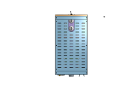
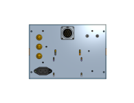
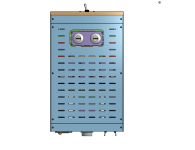
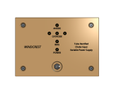
Now I know all the PSU parts on the schematic will indeed fit into the chassis. Since standard amplifiers these days seem to come in a 17 inch width, I made the PSU chassis exactly half at 8.5 inches, about 6 inches high and about 15 inches deep. This way two PSU's will fit exactly under an amp chassis. Most receivers seem to be 15 inches deep, so is this PSU chassis. The big-*** Hammond choke made me go up to 6 inches in height to fit it. Notice the rectifier tubes are enclosed. The two HV diodes are on the bottom HV capacitor board, heatsinked. The only other things that ned to heatsink are the LT1084 regulators and the gyrator choke MOSFET, those heatsink to the side slab, those slabs are 10mm thick aluminum. The Toroidy transformers are obvious, the soft start board, the DC blocker and house ground board is next to the variac on the back panel. Toggle switches on rear for items in the schematic. 3 fuses. The umbilical female socket. The compact variac, etc.
Green in the model indicates this is made from bent stainless or aluminum sheet.
Purple are PCB boards.
The blue side slabs are 10mm aluminum I'll machine on my CNC.
Back panel is plain aluminum.
Front panel is probably going to be Walnut, Zebrawood, etc. whatever nice wood,
Front panel has LED's indicating if all voltages are present and the on/off switch.
The variac control is only accessible if you remove the top panel.
Sample shown is chassis with top removed.
See PDF for all views top, bottom, front, back.
Top view of PSU in that PDF (other views in there):

2025/05/25:
1) Minor changes to the schematic.
2) Uploaded the mechanical design images in a PDF.
Now I know all the PSU parts on the schematic will indeed fit into the chassis. Since standard amplifiers these days seem to come in a 17 inch width, I made the PSU chassis exactly half at 8.5 inches, about 6 inches high and about 15 inches deep. This way two PSU's will fit exactly under an amp chassis. Most receivers seem to be 15 inches deep, so is this PSU chassis. The big-*** Hammond choke made me go up to 6 inches in height to fit it. Notice the rectifier tubes are enclosed. The two HV diodes are on the bottom HV capacitor board, heatsinked. The only other things that ned to heatsink are the LT1084 regulators and the gyrator choke MOSFET, those heatsink to the side slab, those slabs are 10mm thick aluminum. The Toroidy transformers are obvious, the soft start board, the DC blocker and house ground board is next to the variac on the back panel. Toggle switches on rear for items in the schematic. 3 fuses. The umbilical female socket. The compact variac, etc.
Green in the model indicates this is made from bent stainless or aluminum sheet.
Purple are PCB boards.
The blue side slabs are 10mm aluminum I'll machine on my CNC.
Back panel is plain aluminum.
Front panel is probably going to be Walnut, Zebrawood, etc. whatever nice wood,
Front panel has LED's indicating if all voltages are present and the on/off switch.
The variac control is only accessible if you remove the top panel.
Sample shown is chassis with top removed.
See PDF for all views top, bottom, front, back.
Top view of PSU in that PDF (other views in there):
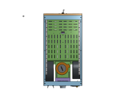
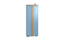
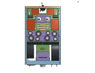
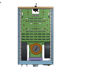
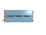
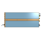
I think I'm settled on the monoblock PSU's electronics and mechanicals. Going with choke input exclusively. Schematic updated. Used PSUII, the ripple is immeasurable at 100mA load. Also ran model with a load change, ending the Pi filer with only 1H virtually eliminated ringing. I think I finalized the mechanicals for the PSU chassis too below: Green is bent sheet metal, blue is anodized aluminum, black are the Toroidy PT's and 16H, 12H chokes, allocated solder tabs space for mains side point to point wiring, red blocks are MKP's, variac, silver are angle brackets, purple are PCB's, brown front is some kind of wooden beauty face TBD, the wood strips down the sides hide the 4 M6 torroid mounting bolt heads in a slot, 5AR4's are given a cute little cutout so you can see them, a row of euro scew terminals separate the AC side from the DC side for serviceability demarcation. Lots of parts, but they do fit into the box which is 394mm deep (15.5 inch) 152mm high (6 inch) and 215mm wide (8.5 inche which is exactly half of a standard 17 inch wide amp which will be the stereo amp chassis width).
Attachments
-
 Top View Cover On.png251.2 KB · Views: 47
 -
 Side View X Ray.png285.7 KB · Views: 54
 -
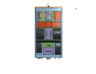
 Bottom View Cover Off.png440 KB · Views: 51
 -
 Top View Cover Off.png437.6 KB · Views: 55
 -
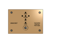 Front View.png345.2 KB · Views: 54
 -
 Rear View.png374.5 KB · Views: 56
 -
 Side View With Bolt Hiding Slot for Wood Insert.png178.9 KB · Views: 54
Last edited:
I wasn't liking the 16 inch depth of the chassis, managed to trim it down to 14 inches (which seems to be what a lot of receivers come). All the parts on the schematic fit with the addition of even more DC link caps. Schematic updated. Some PCB boards were consolidated. Now I know the exact size of every PCB to begin making. All mounting holes/slots are in place. Ready for an order to Send Cut Send for the sheet metal parts they will make, I will probably only wind up making the face plate on my CNC.
Attachments
Wondering if you considered using Damper tubes instead of 5AR4s? You would get a more controlled power up time, and potentially have a greater current capability. Vinylsavour 19DE3
- Home
- Amplifiers
- Tubes / Valves
- Ambitious direct bias PSE 300B with dual PSUs