put a new amp board into the Marantz 1200.
I put a new amp and tube preamp into my Sx-780 dead quiet, more power, awesome sound
The nylon washer may solve the ground loop problem
I put a new amp and tube preamp into my Sx-780 dead quiet, more power, awesome sound
The nylon washer may solve the ground loop problem
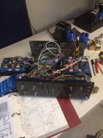
Progress so far-- I've been concentrating on the power amp boards. Yesterday, I used the preamp section to another amplifier and the hum started right away, before the Marantz 1200 speaker relay clicked on. That tells me that the source of the hum is coming from one of the three boards connected to the interconnect board. They are: Phono amplifier board, tone amplifier board and X10 amplifier r board.
What happens if the main amplifier in is disconnected from the pre-amp by pulling the pre-amp out jack from its socket.
Then what happens if you earth the centre of that now free end of that jack to the outer case of the socket from which it has been removed i.e. shorting the signal in of the main amplifier to earth.
As a precaution have one hand free to turn the amplifier off if there is any trouble which might damage the amplifier or the speaker.
Last edited:
Posting #17 shows what happens when I pull the preamp jack and put the center of the jack on the outer case- the hum goes away- for awhile.
The hum is back..I can hear it with the headphones, second set of speaker outputs, turned all the knobs, it just doesn't matter.
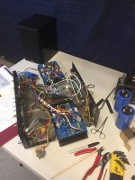
The amp is now torn down and opened up. I'm going to ring out every wire from end to end, check every solder joint. I also learned that copper wire must have been really expensive back in the early 1970s. Seems that most wires are made of stranded steel and there is corrosion (white powdery substance), and some of the soldered joints will fall apart if you breathe on them. Of course I found this out when taking the interconnect board off.
The fun continues...
The hum is back..I can hear it with the headphones, second set of speaker outputs, turned all the knobs, it just doesn't matter.
The amp is now torn down and opened up. I'm going to ring out every wire from end to end, check every solder joint. I also learned that copper wire must have been really expensive back in the early 1970s. Seems that most wires are made of stranded steel and there is corrosion (white powdery substance), and some of the soldered joints will fall apart if you breathe on them. Of course I found this out when taking the interconnect board off.
The fun continues...
Attachments
Does anyone think the shielded wire could cause a ground loop/hum?
When I move the signal wire (the wire from the amp input jack to the power amp board signal in connection), sometimes the hum will go away.
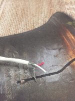
Marantz used some gray wire that has steel braided wire that connects to ground on the jack, and a clear plastic coated wire that carries the signal.
When I move the signal wire (the wire from the amp input jack to the power amp board signal in connection), sometimes the hum will go away.
Marantz used some gray wire that has steel braided wire that connects to ground on the jack, and a clear plastic coated wire that carries the signal.
I once salvaged some TO-3 sockets from a defunct amplifier dating from the 1970's and used them in a project amplifier but this was a totally bad move and I ditched them.Yours look worse for wear than the ones I tossed out about 10 years ago.
Did the bad TO-3 sockets cause the project amp to hum? I've got new sockets I was saving to make a Leach Amp.
If I can't get rid of the hum on this Marantz 1200, I'm going to make a Leach Amp and put the Marantz on the back shelf.
If I can't get rid of the hum on this Marantz 1200, I'm going to make a Leach Amp and put the Marantz on the back shelf.
Did the bad TO-3 sockets cause the project amp to hum? I've got new sockets I was saving to make a Leach Amp.
If I can't get rid of the hum on this Marantz 1200, I'm going to make a Leach Amp and put the Marantz on the back shelf.
From memory there was a problem with dc offset due to poor mechanical contact between the transistors and the sockets. The amplifier has a regulated power supply and a dc protection relay whose contacts are normally open - so no click on if dc was present or click on and instantly off with no hum.
I built a Leach amplifier many years ago, I did not use transistor sockets and had no problems in getting it to work. I think of transistor sockets as an anachronism - it was quite usual to see connections to the pins being made with stiff wire wrapped around them - this too a common practice back in the 1970's when these sockets were in vogue.
You could build the Leach with modern transistors in flat packages like MJL21193 and MJL21194. On-Semiconductor quote especially low THD figures in the datasheet which is worth a look.
First, you better stop using the inter connection cables of pre-amp to power amp, you temporarily solder short wires between the RCA jacks inside the amp, RCA ground(outside) to ground and pre-amp out to power amp in(RCA jack centre to centre), this to avoid any bad contact of the inter connection cable.
Second, your power amp need a relative long audio input cable, your cable seems not so good, it looks like thin without good shielded screen cover signal cable, if like this it is easy pick up noise/hum.
Third, the power amp audio input cables should not tie with other cables together, like the power supply cables which easy pick up noise/hum and never with the amp's output(to speaker) cable this will caused the amp oscillation, the audio input cables should lay stand alone freely and try to keep as far as from the AC lines and the power transformer.
Last, the power amp audio input cables should keep as short as possible, your right channel power amp using a very long input cable(like an antenna), due to the right channel power amp module location, it need a long input cable, so that right channel will easy pick up noise/hum.
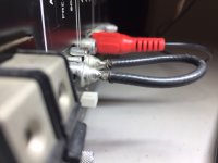
For the power amp input cable problem, please change to a bigger size with good shielded signal cable, soldering the shielding screen wire to the ground, lay the cable short and freely inside the amp, please check the last pic
Second, your power amp need a relative long audio input cable, your cable seems not so good, it looks like thin without good shielded screen cover signal cable, if like this it is easy pick up noise/hum.
Third, the power amp audio input cables should not tie with other cables together, like the power supply cables which easy pick up noise/hum and never with the amp's output(to speaker) cable this will caused the amp oscillation, the audio input cables should lay stand alone freely and try to keep as far as from the AC lines and the power transformer.
Last, the power amp audio input cables should keep as short as possible, your right channel power amp using a very long input cable(like an antenna), due to the right channel power amp module location, it need a long input cable, so that right channel will easy pick up noise/hum.
For the power amp input cable problem, please change to a bigger size with good shielded signal cable, soldering the shielding screen wire to the ground, lay the cable short and freely inside the amp, please check the last pic
Attachments


Hello Patrick101- Thank you for your response. I will try your suggestions. On one channel (the long signal wire), I've been using some two conductor shielded wire, using one wire for the signal, one wire for the ground. The steel braid is not connected to ground. Perhaps that causes the hum??
Mjona- I'm going to build a Leach Amp regardless of if I can fix the Marantz 1200 or not. Thanks for your advice this far.
Mjona- I'm going to build a Leach Amp regardless of if I can fix the Marantz 1200 or not. Thanks for your advice this far.
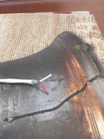
Here's a couple photos of the wire I replaced on the right channel, the humming channel. Red wire is the signal, white wire is ground.
I should use the red wire as signal, steel braid as ground, don't use the white wire (cut it)? I'll give it a try.
I should use the red wire as signal, steel braid as ground, don't use the white wire (cut it)? I'll give it a try.
Attachments
Here's a couple photos of the wire I replaced on the right channel, the humming channel. Red wire is the signal, white wire is ground.
I should use the red wire as signal, steel braid as ground, don't use the white wire (cut it)? I'll give it a try.
You showed some photos of the supply capacitors in an earlier post did you take any others showing how the wiring was routed.
The circuit diagram in the service manual is not much help in following the earth paths as all input and output earths connect to the chassis. You would have to look at the diagram and search the paths to show how and where.
The gauge of wire you have chosen for the power amplifier input connection is a lot for the level of signal involved and using this will make soldering more difficult and as pointed out by patrick101 it is excessive in length.
One of the principles of wiring is to twist pairs together so fields arising from a.c. currents they pass tend to cancel out so you have to be careful with harness wire arrangements and routes. If these are kept bundled there is some memory in wire that gives clues as to previous route if you disconnect them.
Also if the left channel is working properly you should look at the wiring and route for clues as to where things might have gone wrong with the right hand one.
After rewiring the RCA jacks for preamp out and amp in, carefully placing the wires back to their original location- the hum is now on the left side.
As Deafbykhorns mentioned regarding the inputs being grounded, next step is to remove the signal wire inputs and wire them separately, making sure to chassis ground one side per the schematic.
As Deafbykhorns mentioned regarding the inputs being grounded, next step is to remove the signal wire inputs and wire them separately, making sure to chassis ground one side per the schematic.
Attachments
Bad solder joints are the repair man's bread and butter
As I mentioned it is difficult to solder heavier gauge wire to make a decent joint. Also as mentioned you also need to make the joint secure mechanically before soldering - that is don't rely on the strength of solder to glue the joint.
There are holes in the input sockets on which the solder is more grey than silver = signs of oxidation over time which can indicate a joint that has gone "cold". Solder paste is used in printed circuit board manufacture - know what you are dealing with see Solder paste - Wikipedia
I suspect you needed to remove the back cover to get the new input lead in place to solder and the white inner has been soldered to the shield and that for the left channel is not making good enough electrical contact with the earth tab. If there is any resistance in the joint this will drop a voltage across the connection. Moving the back in place could have been sufficient to undo your soldering work.
My advice is to replace the cable with signal and shield with a gauge the will permit the ends to fit through the holes on the input socket tabs. It helps to use something which is flexible as well.
You need a clean surface to tin these tabes - use a solder sucker to remove the bulk and follow that up with a small wire brush to get a surface where the solder will take.
Pre-tin the new cable and thread this through the socket tabs - don't splay the individual wires like a fan.
After rewiring the RCA jacks for preamp out and amp in, carefully placing the wires back to their original location- the hum is now on the left side.
As Deafbykhorns mentioned regarding the inputs being grounded, next step is to remove the signal wire inputs and wire them separately, making sure to chassis ground one side per the schematic.
As I mentioned it is difficult to solder heavier gauge wire to make a decent joint. Also as mentioned you also need to make the joint secure mechanically before soldering - that is don't rely on the strength of solder to glue the joint.
There are holes in the input sockets on which the solder is more grey than silver = signs of oxidation over time which can indicate a joint that has gone "cold". Solder paste is used in printed circuit board manufacture - know what you are dealing with see Solder paste - Wikipedia
I suspect you needed to remove the back cover to get the new input lead in place to solder and the white inner has been soldered to the shield and that for the left channel is not making good enough electrical contact with the earth tab. If there is any resistance in the joint this will drop a voltage across the connection. Moving the back in place could have been sufficient to undo your soldering work.
My advice is to replace the cable with signal and shield with a gauge the will permit the ends to fit through the holes on the input socket tabs. It helps to use something which is flexible as well.
You need a clean surface to tin these tabes - use a solder sucker to remove the bulk and follow that up with a small wire brush to get a surface where the solder will take.
Pre-tin the new cable and thread this through the socket tabs - don't splay the individual wires like a fan.
Last edited:
Good advice Mjona.
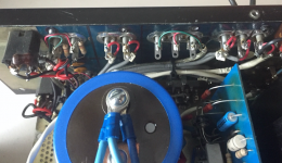
I redid the wires and moved to the interconnect board. Found this red wire from preamp out jack to the interconnect board. (See photo) Repaired the wire and reflowed the solder. Turned the amp on and thought something was wrong because there was no hum!
However, I changed the volume and the hum returned. Turned off the music to check if the volume affected the hum and noted that the hum goes away when the volume is turned up to 3/4 and above- every time.
So, I'll thoroughly study the schematic and touchup all the solder joints on the interconnect board and switches/potentiometers. They are all soldered onto the interconnect board, except for the selector and speaker switches. That selector switch is a birds nest of fragile wires that I'm afraid to breathe on. Schroedinger's Cat Switch.
Finally made some progress.
Last edited:
Good advice Mjona.
I redid the wires and moved to the interconnect board. Found this red wire from preamp out jack to the interconnect board. (See photo) Repaired the wire and reflowed the solder. Turned the amp on and thought something was wrong because there was no hum!
However, I changed the volume and the hum returned. Turned off the music to check if the volume affected the hum and noted that the hum goes away when the volume is turned up to 3/4 and above- every time.
So, I'll thoroughly study the schematic and touchup all the solder joints on the interconnect board and switches/potentiometers. They are all soldered onto the interconnect board, except for the selector and speaker switches. That selector switch is a birds nest of fragile wires that I'm afraid to breathe on. Schroedinger's Cat Switch.
Finally made some progress.
Yesterday 06:58 PM
Attachments

Good advice Mjona.
I redid the wires and moved to the interconnect board. Found this red wire from preamp out jack to the interconnect board. (See photo) Repaired the wire and reflowed the solder. Turned the amp on and thought something was wrong because there was no hum!
However, I changed the volume and the hum returned. Turned off the music to check if the volume affected the hum and noted that the hum goes away when the volume is turned up to 3/4 and above- every time.
So, I'll thoroughly study the schematic and touchup all the solder joints on the interconnect board and switches/potentiometers. They are all soldered onto the interconnect board, except for the selector and speaker switches. That selector switch is a birds nest of fragile wires that I'm afraid to breathe on. Schroedinger's Cat Switch.
Finally made some progress.
Yesterday 06:58 PM
The problem will be due to solder joints. The black outer case cable - the soldering in this looks dodgy - you need all of the wires to be tinned and not splayed out in fan fashion with gaps between the strands.
There is no point in using fancy cable like this tacking on a small solder land on a pcb - this site is not designed for that gauge of wire which looks pretty rigid to the point of any movement after soldering will compromise the work.
If this is the last area you worked on go back there and use your finger to test if the hum goes away when you probe away. Do the same with the volume pot connections to see what happens when you move it.
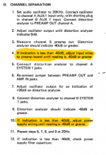
Please see photo for what the service manual says regarding Performance Verification procedure, Part O.
I don't have a distortion analyzer, but will try and borrow one and attempt this procedure. I do have a signal generator and o-scope.
I don't have a distortion analyzer, but will try and borrow one and attempt this procedure. I do have a signal generator and o-scope.
Attachments
Please see photo for what the service manual says regarding Performance Verification procedure, Part O.
I don't have a distortion analyzer, but will try and borrow one and attempt this procedure. I do have a signal generator and o-scope.
If you have reached this stage it appears you have resolved the hum issue in which case with some caution you could look exploring by running sine wave tests into a dummy load and possibly a 10kHz square wave.
- Home
- Amplifiers
- Solid State
- Am I beating a dead horse??