Repaired power amp board on my Marantz 1200 now has a ground loop problem- 60 Hz hum, noise drifts between channels. When I remove the right power amp board/heatsink from the chassis, the hum is gone. Sound hum doesn't increase/decrease with volume, I can move the signal wire to RCA input and the hum will go away, for awhile.
I'm going to remove the board from the heatsink and compare to the other channel, look for solder bridges, etc.
With all the time I've got now that I'm "working" from home, I'm thinking of building a Leach Amp or a Pass DIY amp to replace the Marantz.
Am I beating a dead horse?
I'm going to remove the board from the heatsink and compare to the other channel, look for solder bridges, etc.
With all the time I've got now that I'm "working" from home, I'm thinking of building a Leach Amp or a Pass DIY amp to replace the Marantz.
Am I beating a dead horse?
Build a new one. You will not regret it. It will outperform that oldie, as well. How much power to you need? If 25 or so watts will do, I would build a Pass or First Watt DIY design. If you want 100 watts or more, I would look to a Hypex or IcePower amp module design, or Rod Elliot SS design.
Thanks for your reply.
What would you do with the old one? I really don't want to sell or give it away, too much sentimental value with that old amp. Maybe I'll put it on the shelf and forget about it, build a new one.
What would you do with the old one? I really don't want to sell or give it away, too much sentimental value with that old amp. Maybe I'll put it on the shelf and forget about it, build a new one.
I would say the trusty steed is ailing but still very much alive. Clearly the problem has to be related to something you did. If you can't see anything, ask the multimeter. Verify continuity on each and every ground connection to the power amplifier board, make sure they all go exactly where they are supposed to go, and think about where you might inadvertantly have introduced an extraneous one. Also make sure power supply wiring is properly twisted etc..
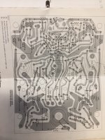
This is an 80 wpc integrated amp from a time when that was well above average. From a modern perspective, the power amp seems overly complicated but I imagine it should be ahead of e.g. a P3A still.
This is an 80 wpc integrated amp from a time when that was well above average. From a modern perspective, the power amp seems overly complicated but I imagine it should be ahead of e.g. a P3A still.
You can't build anything until after you figure out what went wrong on the Marantz you 'fixed.'
You're right- I won't be able to move on until I fix it.
When I remove the right power amp board/heatsink from the chassis, the hum is gone.
Does the hum also go away if instead you remove the left board/sink,
leaving the right one in place?
Hi Rayma- yes, the humming does go away when I remove the left power amp board and heatsink. It also goes away when I remove both boards/heatsinks.
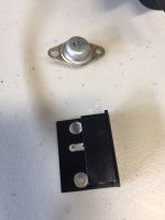
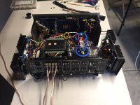
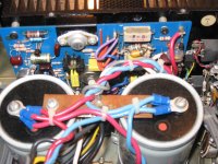
It's possible I may have found the problem- missing nylon washer for the driver transistor. Shown in first photo, top hole is missing the nylon insulating washer. The little heatsink that holds the driver transistor is attached to the power amp board. The driver transistor is connected into the circuit through the hole onto the trace on the other side of the PCB. I'm thinking that it creates a ground loop if the nylon washer is missing?
New nylon washers will be here by Friday.
Attachments
The past two days "working" from home I've spent working on the Marantz 1200 trying to solve the 60 Hz hummmmmmmmmmmmmmmm...
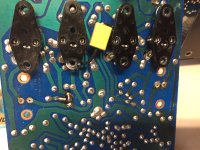
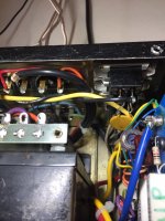
Installed new nylon washers on the driver transistors, replaced the broken connector shown in third photo, above. While attempting to set DC offset and bias, I moved the power amp board/heatsink and grounded out the positive side of the rail. Popped the fuse and got a couple flashes of lightening and a little puff of smoke.
Fifty two volts caused two of the output transistors on the other channel to short, Q801 shorted and R530 smoked- literally. It also smoked pre-driver transistor Q507. Naturally that transistor has CR503 sitting real pretty right above it. It took me most of yesterday afternoon and today to get the amp back to the condition it was in before this adventure began.
As it sits right now- It's a good thing I had all the parts and transistors, except for those little nylon washers. But, it didn't do me any good. The amp still hums when the power amp boards are installed back into the chassis.
When the power amp boards are sitting on the plastic topped table, no hum. If I install the left channel back into the chassis, no hum.
However, if I set the right power amp board on the chassis, it hums, though mostly on the right speaker. If I put both power amp boards in the chassis, it hums.
I'm thinking maybe I'll run long wires to the right channel and place the power amp board next to my preamp power supply? Or, I'll remove all the ground wires one at a time that are connected to the power amp board? (I've already checked all wires for continuity).
Good thing I'm "working" from home...
Attachments
For a little while today, I had it all back together with no hum. Adjusted DC offset on both channels, adjusted bias. Everything was stable and sounded real nice.
After almost 2 hours, started to hear the hum again. Switched inputs, checked DC offset and bias. DC offset on the LEFT channel was about 30mV, right channel was about 5mV. Bias was around 12mV.
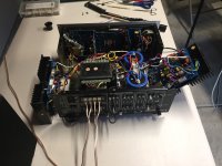
Removed the right channel power amp board and set it on the table like shown on the first photo in post above. Sounds fine again...
I just cannot figure out why the right channel doesn't like being in the chassis?
One other thing- when I touch the DMM probes on the outside of the speaker jacks, I can hear the hum get louder. I tapped on them with a piece of plastic and the hum went away- for an hour or so.
After almost 2 hours, started to hear the hum again. Switched inputs, checked DC offset and bias. DC offset on the LEFT channel was about 30mV, right channel was about 5mV. Bias was around 12mV.
Removed the right channel power amp board and set it on the table like shown on the first photo in post above. Sounds fine again...
I just cannot figure out why the right channel doesn't like being in the chassis?
One other thing- when I touch the DMM probes on the outside of the speaker jacks, I can hear the hum get louder. I tapped on them with a piece of plastic and the hum went away- for an hour or so.
Attachments
The horse is up and kicking- sometimes. When the power amps boards are installed in the chassis and I move the bundle of wires coming from the power amp board, the hum will go away- for awhile.
The only thing that prevents the hum is removing the right power amp board from the chassis and placing it away from the metal heatsink touching chassis metal. Maybe I can make a case out of acrylic?
Next step is to take apart the front of the amp and look for broken grounds on the interconnect board. Maybe Monday while I'm "working" from home.
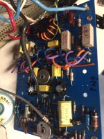
The solder joints on the supply capacitor earth busbar look suspect and the busbar itself does not look original. The result you have is possible when you change the manufacturers earth schemes whether by design or inadvertently.
I would not establish any earth anywhere in a direct line between the two screw terminals as there are 60 cycle current pulses along this length - and the results will feed into the inverting input via the speaker return or the negative feedback decoupling arm and be amplified. These pulses need to be routed to mains earth via the chassis.
Technically speaking you need to establish a T section which is possible using screws and tapped metal pcb spacers and drill a hole through the busbar outside the above mentioned direct line and form a ladder where the rungs are in order of dirtiest first with spacing between other steps leaving the cleanest to last. In that way you will avoid the muddy waters getting into the drinking water. You could make this work using star washers, in combination with doubling up on the nuts so these lock together keeping everthing tight. That would allow wires to be soldered to tags which can be fitted where necessary in the overall construction.
Hi Mjona- That's very interesting that you say that. I noticed when I touch those wires coming off the copper bar that I can hear some pops and crackling noise at times.
The copper bar is original to the amp- but its has been redone by me a few years back because some of the wires were broken. (It is a 50+ year-old amp).
I'm not sure where to drill a hole outside the direct line of the busbar and form a ladder where the rungs are in order of dirtiest first? Or, are you advocating that I should drill a hole in the chassis and create a star ground for all the ground wires on the busbar?
I've attached photos of the busbar before and after my mucking about with it.
Attachments

Hi Mjona- That's very interesting that you say that. I noticed when I touch those wires coming off the copper bar that I can hear some pops and crackling noise at times.
The copper bar is original to the amp- but its has been redone by me a few years back because some of the wires were broken. (It is a 50+ year-old amp).
I'm not sure where to drill a hole outside the direct line of the busbar and form a ladder where the rungs are in order of dirtiest first? Or, are you advocating that I should drill a hole in the chassis and create a star ground for all the ground wires on the busbar?
I've attached photos of the busbar before and after my mucking about with it.
You should retrace your steps in the first instance.
It looks to me that one of your connections is not making proper contact and there are significant differences in disposition of your wiring compare to original. There should have been enough slack to allow repairs if the wires were broken without need for rearranging this.
If you have a dodgy solder joint to the bus-bar there will be some resistance in series with the return wire involved. Current pulsing through such resistance will result in a small amount of voltage which will be amplified.
Looking at the photo as original the red and blue wires are physically close to the bus-bar and run roughly parallel over some length. These are anchored with cable ties to keep them in place so. There will be some magnetic field cancellation because of this and the overall scheme should have been retained.
Also in this the wires to the bus-bar are close to the outside edge of the parallel sides. The line of least resistance between the capacitors will lie in the boundaries of straight lines between the screws attaching to the capacitors.
The wire attachments should be outside of that zone.
To attach these pre-tin the wire leads and the bus-bar copper so you get a shiny solder deposit onto this. It will take some heat to do this.
When you bring the wire to the solder on the board the joint needs to be good mechanically so some pressure will need to be applied until the joint cools. You might need to add a little solder to the join at that point of the under mechanical pressure - use pliers or metal clamps. These too will absorb heat.
The replacement capacitors look too tall in the chassis and there is not enough stretch in the wiring. If so you should consider replacing them with ones that fit in terms of size.
Computer grade types may be good but not if they are physically too big. If these have greatly increased capacitance then the charging pulses could also be higher in magnitude even if the ripple rating is higher.
Thanks, Mjona! I broke out the big guns today, the big soldering iron and reattached the wires using the original holes. The amp still buzzes.
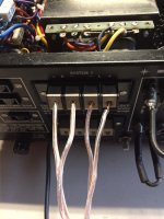
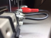
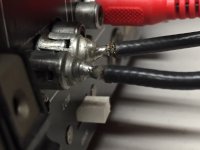
Started poking around with a wooden chopstick and the hum went away for awhile. Decided to try some different RCA connectors for the Amp In and Pre Amp Out and found this wire when stretched makes the hum go away. See how the shielding is broken on one connector?
Started poking around with a wooden chopstick and the hum went away for awhile. Decided to try some different RCA connectors for the Amp In and Pre Amp Out and found this wire when stretched makes the hum go away. See how the shielding is broken on one connector?
Attachments

Thanks, Mjona! I broke out the big guns today, the big soldering iron and reattached the wires using the original holes. The amp still buzzes.
Started poking around with a wooden chopstick and the hum went away for awhile. Decided to try some different RCA connectors for the Amp In and Pre Amp Out and found this wire when stretched makes the hum go away. See how the shielding is broken on one connector?
You can do a lot with a digit(al) detector and a chopstick.🙂
The amp is still alive and working, but still humming- sometimes.
I'm thinking about removing all the ground paths and reconnecting one by one to see if I can fix it. At least it gives me something else to do while "working" from home.
No one can accuse me of wasting time. I'm all caught up on the honey do list, for the first time in 30+ years.
I'm thinking about removing all the ground paths and reconnecting one by one to see if I can fix it. At least it gives me something else to do while "working" from home.
No one can accuse me of wasting time. I'm all caught up on the honey do list, for the first time in 30+ years.
Progress so far-- I've been concentrating on the power amp boards. Yesterday, I used the preamp section to another amplifier and the hum started right away, before the Marantz 1200 speaker relay clicked on. That tells me that the source of the hum is coming from one of the three boards connected to the interconnect board. They are: Phono amplifier board, tone amplifier board and X10 amplifier board.
I'm thinking that it's a bad capacitor on one of these boards? The sound is only coming through the right channel, so I'll read the schematics carefully to try and determine which capacitor it might be. Also, all the electrolytic capacitors were replaced by me in 2013. But I have already found a couple of lifted traces. I also have new caps.
Would a bad transistor/failing transistor cause a humming sound? I don't want to have to pull and test each transistor if I don't need to...
- Home
- Amplifiers
- Solid State
- Am I beating a dead horse??