Recom / need to replace the 0,47uF 100V film caps
The update of the Altec 9440A power amplifer almost finished.
Any recommendation also to replace the 0,47uF 100V film caps on the driver boards (3 on each board).
I assume these are metalized capacitors. What to replace with polypropylene film and foil or is it just a waste of money.
Do these age ?
The update of the Altec 9440A power amplifer almost finished.
Any recommendation also to replace the 0,47uF 100V film caps on the driver boards (3 on each board).
I assume these are metalized capacitors. What to replace with polypropylene film and foil or is it just a waste of money.
Do these age ?
They won't have aged as such. A lot depends on the caps function in the circuit as to whether or not there might be sonic gains. My instincts say probably not worth it, but if you believe there might be, then only you can make that decision.
Hey Guy's!
First i want to thank you for this great thread! i found a lot of useful information here!
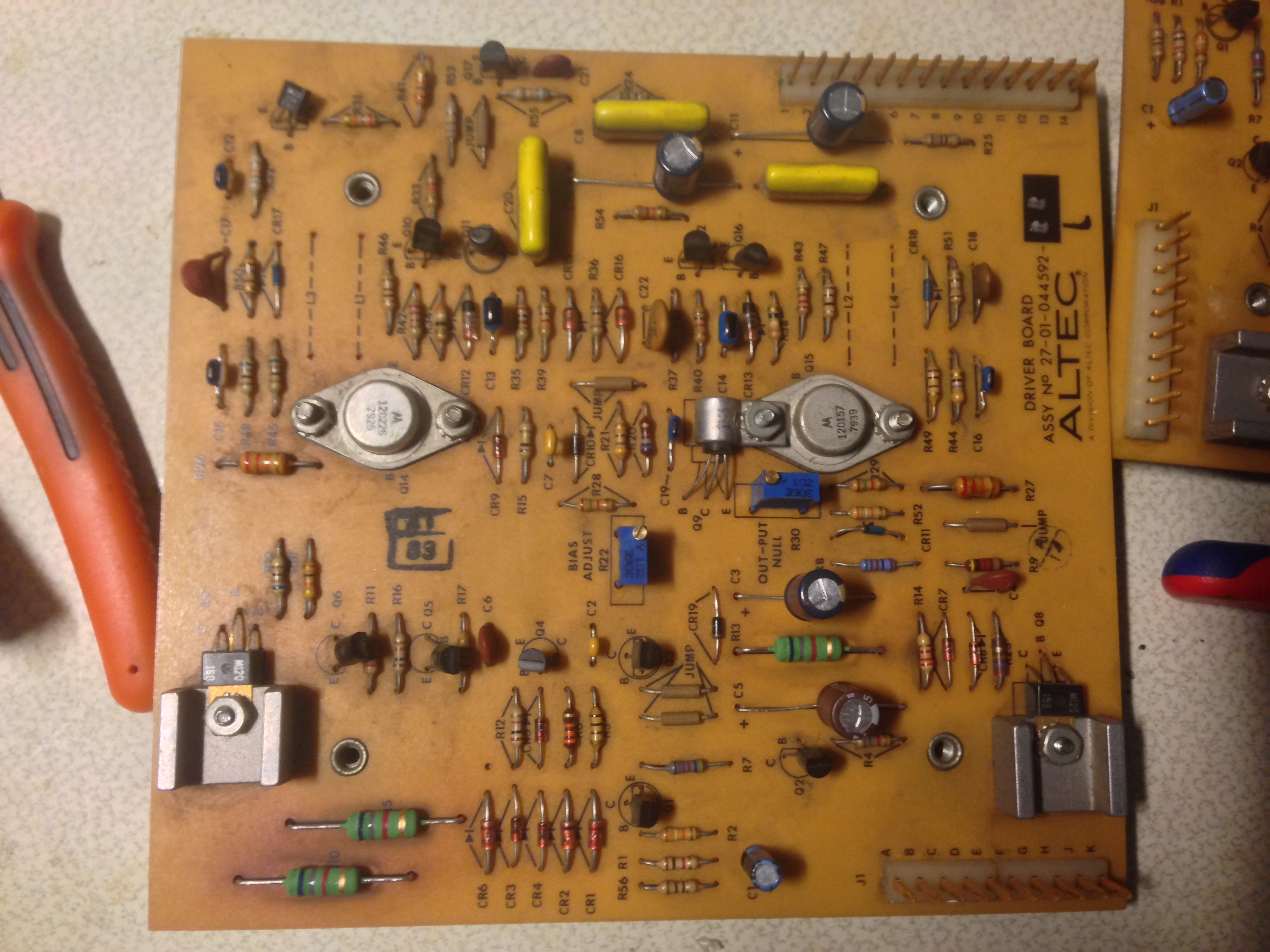
I recaped a 9440A - i replaced all electrolytic capacitors in the amp as well as some of the ceramic types on the driver board. I also installed new trim pots on the driver board.
i followed the advice of djk and increased C10 & C11 to 22uf, i also put 100nf film types parallel to C1 and C3.
the problem i have now is that the amplifier sounds very distorted, and like a hp filter is inserted in the signal path. it was possible to trim the bias on ch2 to the correct value, but on channel 1 there was no reaction when i turn the trim pot, the bias current stays at the incorrect value at about 30ma.
channel one also sounds more distorted than channel two.
do you guy's have any suggestion what the fault could be?
i would really appreciate some help - i spended a lot of money and time i this project, and now i'm really frustrated.
thanks & regards,
george
First i want to thank you for this great thread! i found a lot of useful information here!
I recaped a 9440A - i replaced all electrolytic capacitors in the amp as well as some of the ceramic types on the driver board. I also installed new trim pots on the driver board.
i followed the advice of djk and increased C10 & C11 to 22uf, i also put 100nf film types parallel to C1 and C3.
the problem i have now is that the amplifier sounds very distorted, and like a hp filter is inserted in the signal path. it was possible to trim the bias on ch2 to the correct value, but on channel 1 there was no reaction when i turn the trim pot, the bias current stays at the incorrect value at about 30ma.
channel one also sounds more distorted than channel two.
do you guy's have any suggestion what the fault could be?
i would really appreciate some help - i spended a lot of money and time i this project, and now i'm really frustrated.
thanks & regards,
george
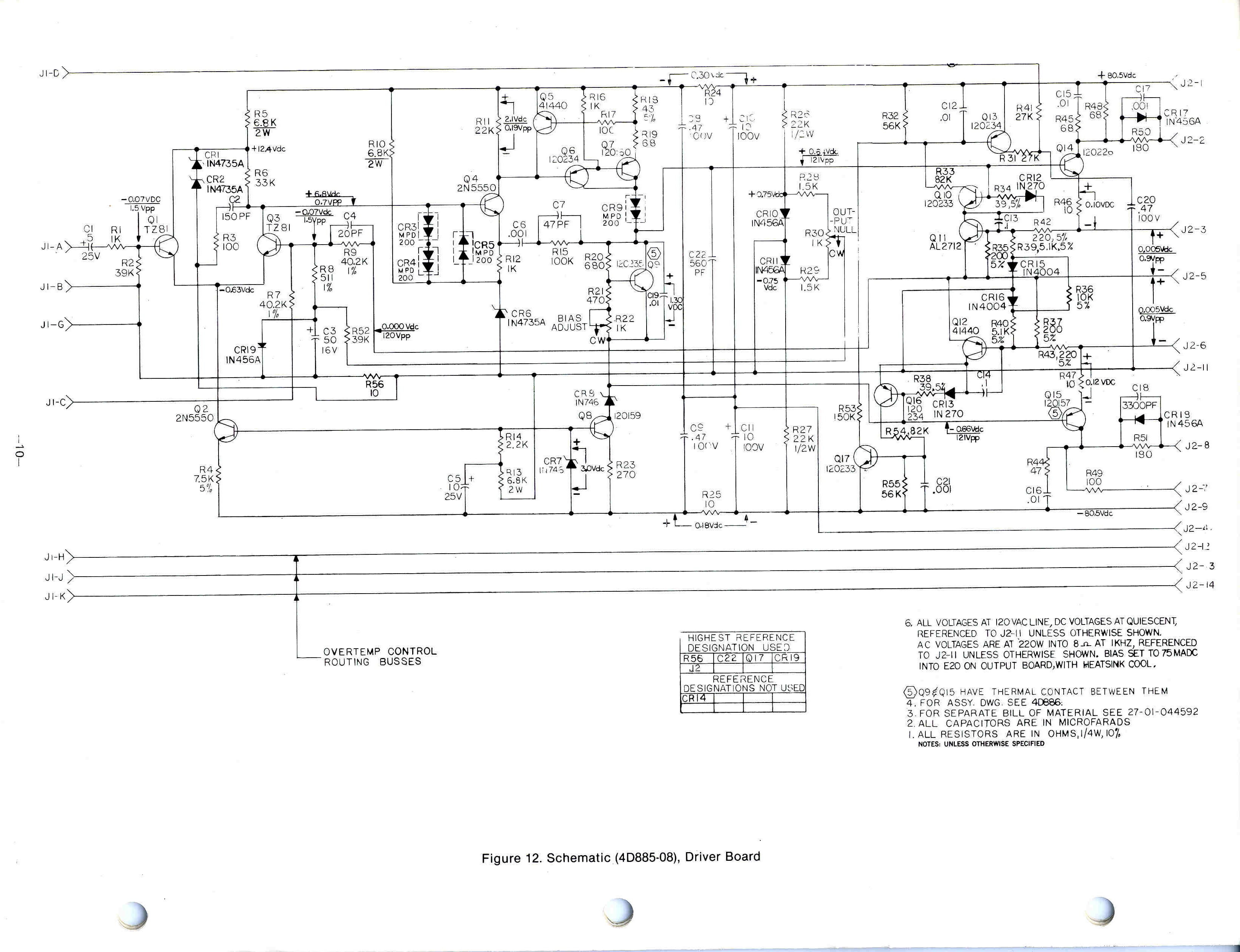
The bias issue sounds like a pure DC type problem... would need to see the circuit to advise on that.
Sounding like a high pass filter is inserted... so no bass ? On both channels or just the faulty bias one ?
Have to ask... was the amp working correctly before you modded it ?
Sounding like a high pass filter is inserted... so no bass ? On both channels or just the faulty bias one ?
Have to ask... was the amp working correctly before you modded it ?
The bias issue sounds like a pure DC type problem... would need to see the circuit to advise on that.
Sounding like a high pass filter is inserted... so no bass ? On both channels or just the faulty bias one ?
Have to ask... was the amp working correctly before you modded it ?
thanks for your reply.
The "hp-fault" occurs on both channels, it doesn't Sound like a real hp filter: the bass is extrem low in Level compared to the hi-mids.
channel one Sound even more distorted than channel 2, but booth channels really sound extrem crappy.
yes the amp worked correctly before service.
today i'll change the Driver boards on the recapped amp against original ones (i've another 2 of this amps on my workbench), to find out if the fault is on the driver board.
what i tried after my last post was to change the input transformers, but also that didn't helped.
so any suggestions are welcome. i'll post links to the schematics in the evening.
regards,
georg
The fact the amp worked OK before means this is a problem caused by the rebuild/mods.
Although logical fault-finding is still the answer it becomes so much more difficult because we could be looking for incorrect values and/or problems with accidental shorts (solder blobs) and so on.
Although logical fault-finding is still the answer it becomes so much more difficult because we could be looking for incorrect values and/or problems with accidental shorts (solder blobs) and so on.


i don't think that the problems are caused by incorrect values. when i recap something i unsolder the old component and solder in the new component - always one by one. i think this is the best way to exclude faults. i double check every print before mounting.
it wasn't possible to find the exact same value for all caps, but the deviation is minimal. for instance 15 uF instead of 16uF regarding the NP Caps on the controller board. or 4.7uF instead 5uF (input coupling cap).
thanks for posting the output board schematics djk - but i don't think that the fault is there - i didn't touched this board.
anyway: i'll change the driver boards against original ones today to see if the fault is on this print.
regards,
george
i found the problem. it was my mistake: i used a wrong value for C2 on the driver board. this caused the distortion.
but the another interesting thing was that also the 100nf film type in parallel to the input coupling cap caused distortion. i found it out during the recap of the 2nd amp. i tested the driver board after every new component i soldered in.
very strange failure, because this mod seems to work for the other guys on this board which recapped this amp.
regards,
george
My 9440A was working, I thought the On/Off switch was faulty, but it was the Triax. I have replaced them all, and after about a week, 2 went bad. I ordered more, waiting. My control board's lamps were about half burned out. I ordered new ones, that were not correct and I fried some stuff on the control board. I have been going thru and trying to replace everything, however I can't find a 16uf Cap 50v NP (C7,8) along with the SCR C103YY .8a, 60V, and the Stabistor STB-567. ANY substitutes of ideas? I consider myself a novice at best. I know how to read schematics and am replacing everything I can on the control board.
Once I finish there I will look to replace all the caps in the amp
Once I finish there I will look to replace all the caps in the amp
Last edited:
Update. Well, after installing a couple new Triacs, and fixing a broken solder path, my amp now blows the 10amp fuse the minute it is turned on. I am going to now remove the front control board and give a good going over. I see how fragile the paths are.
Hi Masterofsparks.
I have a 9440 my self and I did take all apart and checked every bit.
It's Worth the job.🙂
About the 16uF NP cap - 15 uF is ok. I soldered in 15 uF NP audio PP caps.
I read in some forum that the stabistor could be replaced with a 1N4148.
I was a bit sceptic, with all rights. It didnt work, so you can skip that part.
I am lucky because I have one scrapped amp to get parts from. Therefor I do not have any suggestions how to find replacement parts.
If you have blown the Contol PCB - also check Q1 to Q9.
The boards are very fragile, so also the thin copper lines.
Check the big caps in the powersupply and the rectifiers.
Also measure that the trannies are'nt shorted to heatsink.
Then check the outputboard transistors as described in the manual.
Just be damned shure to connect the PCB connetors right, or there will be smoke and Lightning
I have the full service manual on my computer, but sadly I could not upload.
But I guess google can help you 🙂
Best regards:
Figge
Thanks for replying, Figge. I, too DID have another 9440A, however it was stolen from my storage locker. I always am hoping to see someone post it online. Anyway, so are you saying there is no replacement for the stabistor? I have the schematics that are online at Altec Amplifiers
Today, I have completely removed the control board and am going over it closely, I have already replaced most of these parts, I need to check continuity everywhere, as I see how fragile the board is. I had my amp working great, until I put the wrong bulbs in and smoked the control board. Not the easiest project to use as my first real project.
Today, I have completely removed the control board and am going over it closely, I have already replaced most of these parts, I need to check continuity everywhere, as I see how fragile the board is. I had my amp working great, until I put the wrong bulbs in and smoked the control board. Not the easiest project to use as my first real project.
Hi Kurt.
I emailed you but I got a message that there was a problem, so I hope you get it.
Searched for stb 567 and it seems to be a zener-type with 1,6 Vf, 400mW.
Should'nt be to hard to find I guess.
About the bulbs - what type did you put in there ?
If you look in the schematic ther's a bunch of Components in the light Circuit.
It's supplied by an AC voltage, but I dont remember how much.
Is it possible that something else happened, a second damage so to speak ?
Godnight.
//Figge
That's what I'm thinking as well. I have it all unhooked and am waiting on parts from Mouser. Don't know if there are better places or ??? I'd have to check what bulbs I put in that were wrong. I now have the proper lamps. I think they have 387 written on them 28vm40ma.
Thanks for helping me with the Stabistor. I'm still learning about electronics, my father was a wiz, but I wasn't living near him, and now, he has passed. I have all his TV repair tools, Heathkit everything, scope, Transitor/diode tester, signal tracer, etc. I've repaired my tube Ampeg SVT bass head,much easier for me to understand.
Thanks for helping me with the Stabistor. I'm still learning about electronics, my father was a wiz, but I wasn't living near him, and now, he has passed. I have all his TV repair tools, Heathkit everything, scope, Transitor/diode tester, signal tracer, etc. I've repaired my tube Ampeg SVT bass head,much easier for me to understand.
Good evening Kurt.
I hope that the emails worked.
Printing in A3 format works fine. A4 are 😱 and paper is paper - not like a computer...
I have been looking for a replacement for stb 567 🙁
The test-solution may be two diodes in series with a suitable resistor. Ex: 2 pc with 0,8 Vf, or 1 pc 1 Vf and 1 pc 0,6 Vf.
Pull up the voltage to the specified 10mA and measure voltage drop.
Time for bed 🙂
//Figge
Edit: Forgot to mention that resistor is just for measuring Vf@10mA.
Last edited:
djk:
Do you have any suggestions ?
//Figge
Yes but I haven't found any good direct replacement.The STB 567 is just a two-pellet diode, 1.61V at 10mA.
Do you have any suggestions ?
//Figge
Digi-Key has surface-mount series connected diodes that look like they might be OK.
http://www.mccsemi.com/up_pdf/MMBD7000%28SOT-23%29.pdf
http://www.mccsemi.com/up_pdf/MMBD7000%28SOT-23%29.pdf
- Status
- Not open for further replies.
- Home
- Amplifiers
- Solid State
- Altec 9440A... suggestions?