So I've been amazed at all the info on tapped horns and am trying to put something together for a friend of mine who is doing a live music/recording/home theater room.
Requirements:
Room size is 20' x 25'
Mains cover down to about 55, but for the levels we want, we'll probably cross around 75 or so.
It will be used 80% for live recording/rehearsal and mix review. the other 20% will be messing around with a home theatre.
The main objective is to have a serious amount of impact and "feel it in your chest" type bass (similar to what you might get at a night club venue). I figured somewhere in the 130db range would be nice.
The Alpine SWS-15D2 looks very appealing based on what I've seen what with the Xmax and Klippel and general good build quality. I remember having one back in the day. One thing no one has mentioned is that I believe them to have very stiff cones. Should help with the compression loading. I know "very stiff" isn't exactly scientific, but rigidity wise I'm sure it's loads better than things like the Dayton Reference, Pro audio PA cones, and poly cones and such.
Anyways, this is a design I've come up with so far. Any thoughts or analysis would be great. I may have missed a few things.


That's with 500 watts I believe.
Requirements:
Room size is 20' x 25'
Mains cover down to about 55, but for the levels we want, we'll probably cross around 75 or so.
It will be used 80% for live recording/rehearsal and mix review. the other 20% will be messing around with a home theatre.
The main objective is to have a serious amount of impact and "feel it in your chest" type bass (similar to what you might get at a night club venue). I figured somewhere in the 130db range would be nice.
The Alpine SWS-15D2 looks very appealing based on what I've seen what with the Xmax and Klippel and general good build quality. I remember having one back in the day. One thing no one has mentioned is that I believe them to have very stiff cones. Should help with the compression loading. I know "very stiff" isn't exactly scientific, but rigidity wise I'm sure it's loads better than things like the Dayton Reference, Pro audio PA cones, and poly cones and such.
Anyways, this is a design I've come up with so far. Any thoughts or analysis would be great. I may have missed a few things.
That's with 500 watts I believe.
Last edited:
It is +/- 2 db in it's used pass-band (26-75hz). That said, the response is a little ragged. I had an alternative that doesn't extend as low, but it's a little more sensitive without as many peaks. In a 1.0Pi space (not 2.0pi shown) where it will sit it does nearly 130db average.


Looks like about 32-90hz range.
An externally hosted image should be here but it was not working when we last tested it.
Looks like about 32-90hz range.
Last edited:
Update:
I came across an MTX 9500 15" for only $250. This was used in the TH-50 I believe which was a pretty good horn.
Any thoughts?
I came across an MTX 9500 15" for only $250. This was used in the TH-50 I believe which was a pretty good horn.
Any thoughts?
In 1pi space, Xmax is limited to a theoretical 125 Hz, so you’ll need at least two drivers in ~543 L net to hit 130 dB.
GM
GM
I know MTX was used in some, but don’t know which models were used. I did some sims of other MTX drivers though since they had close enough specs to what I was looking for and all looked promising except price.
Hmm, MTX9500 appears to be a series, so which one are you contemplating?
GM
Hmm, MTX9500 appears to be a series, so which one are you contemplating?
GM
Anyways, this is a design I've come up with so far. Any thoughts or analysis would be great.
1. This driver's fs is pretty low for the tuning you want. This driver seems happier in a tapped horn tuned lower than you've shown.
2. It's going to be almost impossible to actually build what you've simulated. You've got S2 in a pinch point - look at the schematic to see what I mean. It's very difficult to mount a driver in a place where the cross sectional area changes unless there are two drivers or unless you are willing to live with a bit of dead space inside the enclosure.
3. Your sim shows CON segments. That's not a big deal at this point but when you get around to the folding part you might want to switch to PAR segments so you can actually accurately build what you simulated.
Last edited:
Points 1 and 3 are good, but a folded horn can be laid out using a narrow S2 compared to S1 with no great difficulty.2. It's going to be almost impossible to actually build what you've simulated. You've got S2 in a pinch point - look at the schematic to see what I mean.
It's very difficult to mount a driver in a place where the cross sectional area changes unless there are two drivers or unless you are willing to live with a bit of dead space inside the enclosure.
The example below would have S2 near the center of the cone, the right side would be S1, the S2 "pinch point" can form a bend in another portion of the horn with no "dead space".
DSL does this on two of their most popular TH 😉.
Art
Attachments
It's a T 9515-44.
With a max usable ~12.6-80.76 Hz design BW and likely narrower with measured specs, it’s a very poor choice for your app, though a decent one for a true sub.
GM
DSL does this on two of their most popular TH
To very good effect, I might add, so another 'piece of the puzzle' to solve for converting a ~reactance annulled FLH to a TH. 😉
GM
Points 1 and 3 are good, but a folded horn can be laid out using a narrow S2 compared to S1 with no great difficulty.
The example below would have S2 near the center of the cone, the right side would be S1, the S2 "pinch point" can form a bend in another portion of the horn with no "dead space".
DSL does this on two of their most popular TH 😉.
Art
Technically you are correct, and therefore normally I would agree with you but not in this case.
In this particular case he's showing S1 at 4.5x the csa as S2. So assuming normal construction methods your drawing isn't scaled right, your drawing is closer to 2:1 (S1:S2). The drawing I've attached below would be closer to the right scale for this sim, and it's not that easy to work with.
An externally hosted image should be here but it was not working when we last tested it.
DSL did it differently when they did this. They used 2 drivers, so they could put one driver on each end of the pinch point. This allowed them to use the "flare" at the throat as a corner reflector for the last bend in the horn. In this case (when only using one driver) the "flare" in the throat is on the wrong side to be used as a corner reflector in the last bend, if it's used as a corner reflector at all it will be in a bend occurring fairly early in the horn flare where it is too big to be used as such. (If this last part is unclear I can draw a picture of the whole horn to make it more clear.)
Attachments
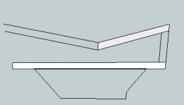
Here's another picture to make things more clear.
Danley style dual driver on the left and a single driver fold on the right.
The dual driver allows you to place the throat flare in the last bend of the horn. The single driver forces you to put the flare on the other side, where it occurs fairly early in the horn, and where it's a bit big to be used as a corner reflector.
Also, as mentioned, the 4.5:1 (S1:S2) in this sim makes the throat flare very large and the wrong shape to be used as a corner reflector.
There may be several ways to fold this horn and I've only shown one possible folding but no matter what you do, using a single driver and a throat flare will result in the throat flare being closer to the throat side than the mouth side where it could be more easily be made to act as a proper corner reflector.
An externally hosted image should be here but it was not working when we last tested it.
I have no practical experience with this yet (in fact I was about to start a thread on how to model enclosures that use 2 drivers with an s1/s2 style similar to the th812).
However, Isnt it safe to assume that we dont have to think about this in 2d only? He could theoretically reduce the "width" of s2 to reduce the overall area of the horn segment, in the exact opposite way that Ricci reduces the width in the S1 segment of his Othorn Tapped horn.
this also means he could expand the first segment of s2/s3 by increasing the width back to the distance between sides for the first segment of the flare (with careful panning), and have the 2 internal panels that are generally the flare set to parrallel (or whatever workst to insure the cross sectional area increases at the correct rate).
shouldnt he change his segments to par as well?
Last edited:
Thanks for the discussion guys.
That flare would actually work in my case since I'm only doing 1 fold. Long rectangle acting as a bench.
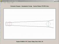
So someone sent me a link on the new dayton audio driver:
It models much better than the Alpine:
Dayton Audio PA385S-8 15
Tapped Horn (Note this is now 1.0Pi space and this is limited to 500 watts which is about 12-13mm driver displacement. That should be manageable with an 11mm xmax).


That flare would actually work in my case since I'm only doing 1 fold. Long rectangle acting as a bench.
So someone sent me a link on the new dayton audio driver:
It models much better than the Alpine:
Dayton Audio PA385S-8 15
Tapped Horn (Note this is now 1.0Pi space and this is limited to 500 watts which is about 12-13mm driver displacement. That should be manageable with an 11mm xmax).
This is pretty impressive and if there is enough room gain from 45hz and below then EQ can be taken out to allow even more power handling.
At this point I'm torn between this horn and 2 of the Alpine type S in a simple ported configuration. They would do 130db with a -3db down point of about 24hz in a 6.5cu ft box. Albeit that's at 650wrms/side vs their rated 500, but it would likely rarely be used at all.
The comparison would be:
Large 13cu ft box, $200 Dayton driver, very high sensitivity with only a need for a 500-700wrms amp mono.
Smaller 6.5 cu ft box, $240 for 2 15" drivers, similar power handling, flatter response and extends lower. Requires 1200wrs of power.
It's a tossup. I'm leaning towards the horn.
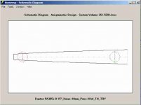
Hi mtnickel,
When I look at the Hornresp Schematic Diagram, this does not look quite like a single fold to me. You are modifying both, the S1/S2 and the S3/S4 volumes. I'll attach a schematic window using your simulation data, and a single fold schematic using the same length, S2 and S3.
Do you have a wood layout/fold to look at?
Regards,
Attachments
Thanks for the discussion guys.
That flare would actually work in my case since I'm only doing 1 fold.
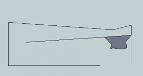
If you are doing only 1 fold I can't see any way to actually build what you simulated. Check the picture below, the center of the driver needs to be mounted to the point shown with the red arrow. How are you going to mount that driver there? And the issue tb46 pointed out is a problem as well.
An externally hosted image should be here but it was not working when we last tested it.
It's a tossup. I'm leaning towards the horn.
It's not a tossup since the horn will have several, if not more, less dB of thermal power compression.
GM
The OP's sims other than in #1 have less than a 2/1 difference in area between S1 and S2, though that is immaterial to the way a single fold could be done and still have S1 larger than S2.If you are doing only 1 fold I can't see any way to actually build what you simulated. Check the picture below, the center of the driver needs to be mounted to the point shown with the red arrow. How are you going to mount that driver there? And the issue tb46 pointed out is a problem as well.

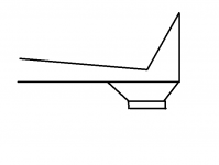
They could be built similar to the sketch below with a single fold.
With a keystone shaped exit larger on the left side, the widening of the horn towards the mouth could be approximated.
Attachments
Last edited:
They could be built as below with a single fold.
Ok, I guess it's possible, but IMO that's a huge amount of wasted space. I won't call it "dead space" because it's not inside the enclosure but it is a massive amount of wasted space outside the enclosure, space that could be used if it were a rectangular shaped box.
Anyway, my point here is that the throat flare is not THAT important that it should come at the expense of wasted space. And if it is determined to be THAT important, it can be done easily if two drivers are used, it becomes problematic when you try to do it with one driver.
Last edited:
- Status
- Not open for further replies.
- Home
- Loudspeakers
- Subwoofers
- Alpine SWS-15D2 Tapped Horn