I haven’t tried yet. In my Navy experience, we just swapped entire boards. The defective boards were shipped to a repair depot or the manufacturer.
I just spent a couple hours testing again and at this point, I am scratching my bald head.🙂 I borrowed a Rigol portable 12 bit scope from a friend and looked at the waveforms coming out of the Quant Asylum analyzer while I ran the distortion and THD tests on each channel.
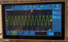
First I tried a simpler test by just feeding a 1kHz sine wave into each channel with only the scope connected. All 4 channels had a fairly clean sine wave output. With this 12 bit scope, I can see the switching frequency of the Alpine riding on the sine wave which is kind of cool.
Here is the part I can’t understand. When I connect the Quant Asylum analyzer and ran the distortion tests, once again 2 channels looked good and 2 didn’t with very high noise floor. I then looked at channel 4 with no signal but the QA403 still connected. I have attached a screenshot of what I measured. It is an approximately 2.5 Volt RMS sine wave at 154-155 kHz. When I disconnected the QA403, this signal disappeared and the Channel 4 output only showed a very low amplitude sine wave at the Alpine switching frequency.
I can’t see any reason why 2 channels would be showing this ~2.5 volt RMS signal with QA403 connected but no signal coming out of it and 2 channels do not show this signal that is obviously the cause of the high noise floor on the channels I am calling bad. I am using shielded BNC coax cables with RCA adapter on the amplifier end.
One last thing. The 2.5 volt signal I am calling noise is with the gain set at the mid point on the Alpine. The amplitude of this signal varies with the gain setting.
I really like this little Rigol scope. I think I am going to sell or donate my handheld Owon scopemeter and buy this Rigol. It can be powered by a USB C power bank or an AC adapter with USB C output.
Attachments
It's always good to have an extra scope.
In some alpine amps, the 2v of noise is normal but it's generally on all channels and simply leakage through a cheap output filter. In some instances (most?), the output noise is determined with a A or C-weighting.
If the noise is leakage from the carrier through... whatever, could you possibly add a few caps or RC networks to damp the noise?
Are the noisy channels definitively audibly distorted (could pick them 10 out of 10 times in a blind AB test)?

The PDX already has what look very much like bypass caps and RC networks that I assume are filters on the input buffers. I have the service manual and can see this on the schematic. This 155 kHz signal is being amplified when the QA403 is connected to the input so I am thinking this carrier is coming from the QA403 or something in the environment.
I am going to try driving a pair of NHT tower speakers with the 2 suspect channels to see what I can hear and if it is audibly distorted.
I am going to try driving a pair of NHT tower speakers with the 2 suspect channels to see what I can hear and if it is audibly distorted.
Could the input circuit of the analyzer be destabilizing the amp?
If you connect the analyzer and a dummy load, do you see the same problem?
If you connect the analyzer and a dummy load, do you see the same problem?
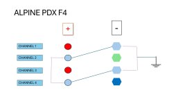
I circled back to something you said related to how the speaker level outputs are bridged. I am still trying to figure out how this noise is coupling in on channels 2 and 4 and not on channels 1 and 3. I used an ohm meter to figure out what is connected to what.
Channel 1 negative, Channel 2 positive, Channel 3 negative, and Channel 4 positive are all at same potential and connected to the 12 VDC input to the power supply. Still not clear to me why the noise is coupling in but I am still thinking on this.
Channel 1 negative, Channel 2 positive, Channel 3 negative, and Channel 4 positive are all at same potential and connected to the 12 VDC input to the power supply. Still not clear to me why the noise is coupling in but I am still thinking on this.
Attachments
I also found a thread on Steve Meade Designs forum from more than 10 years ago where a PDX F4 owner desribed something similar when he tried to use the DD-1 to set gains. He was having problems with distortion on channels 2 and 4 but he did not have a scope to show what it looked like. He did not post a solution. This is leading me to believe this is normal behavior. Still don’t understand why the Quant Asylum and SMD devices are part of the problem and my oscilloscope is not.
What shows up on a scope isn't necessarily audible. 155kHz isn't audible. It can SOMEtimes cause audible issues but it's not, itself, audible.
Did the DD-1 show distortion that he didn't hear before he tried using it?
Did the DD-1 show distortion that he didn't hear before he tried using it?
I have not hooked it up to my home stereo speakers yet. Will do that today. The small test speakers I was using are not very revealing.
The DD-1 user did not report what it sounded like. His description was not very good. There was just enough there for me to think it was the same issue.
Thinking out loud here. Only channels 2 and 4 appear to amplify the noise signal along with the sine wave test signal. Those channels positive connections are tied to ground. If the noise is coupling on the amplifier ground, could this be why those 2 channels exhibit this behavior?
In some instances, you need to listen to the amplifier through headphones (properly protected) with a dummy load (or speaker load) across the output to hear the most subtle of problems... Then again, if that's that subtle, are they a problem.
Some amplifiers are less stable with one type/ohm load than others. Very reactive speakers, especially those with passive crossovers that don't have impedance compensations networks can cause more problems than others.
But isn't the problem on the other amplifier different channels?
Some amplifiers are less stable with one type/ohm load than others. Very reactive speakers, especially those with passive crossovers that don't have impedance compensations networks can cause more problems than others.
But isn't the problem on the other amplifier different channels?
I am pretty sure the problem on the other amplifier is with the same channels. I am going to retest it to verify. I have not had time to set up to listen to the amp yet. I was doing stuff with my 18 year old this afternoon.
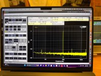
I did just try something that had an interesting result. The QA403 has ability to test single ended or differential output and input. I ran the distortion test with differential I/O and the high frequency noise is gone. I also tested each channel with a 1 kHz sine wave and the scope traces looked good for each channel.
The test was not all good. There is much more prominent AC powerline noise in the FFT running in differential mode. Picture is attached. First one is with differential i/O. All 4 channels looked like this with differential test.. Second is single ended on channel 1 from earlier test for comparison.
Bottom line is it appears the amps are OK. Now I have to figure out the 60 Hz but I believe that is due to how sensitive the QA403 is and my jury rigged test cables.
I just borrowed a current Alpine amp which is also Class D 100 watts per channel and am going to run the same tests to compare. I also have some old Soundstream and Zapco A/B amps that I will test and compare. The Soundstreams are D100 II and D200 II. Zapco is a DC Reference 1000.4.
Attachments
I measured the other PDX F4 and got the same results. With single ended connection between channels 2 and 4 speaker outputs and QA403, I had tons of noise and distortion, With differential connection, the noise is gone and distortion measurements match channels 1 and 3. 1 and 3 measure good even with single ended connection. This has to be related to the fact that Channels 2 and 4 positive speaker output is at the amplifier ground potential.
From what I remember about electrical design, an RC filter shunts high frequency noise to ground because the RC network is lower resistance to the higher frequencies. Channels 1 and 3 are shunting the high frequency noise to amplifier ground. Channels 2 and 4 are not - at least in my measurement setup. Perry, i think this goes back to something you suggested early on - try reversing the + and - lines going to the analyzer for channels 2 and 4. I thought simply flipping the PDX speaker connectors would do that but it doesn’t. No matter how you plug them in, The positive and negative speaker connections stay the same. It works the same way as a circular power plug where + is almost always the inside center connection.
The noise signals are way above 100 KHz and above human hearing but they do distort the output measurement and — in the case of channels 2 and 4, they come back in through their preamp inputs with my initial single ended measurement setup.
It is worth mentioning that I live ~100 yards from a Fire/EMT station. There is cell phone tower on their property as well as powerful FM transmission antennas. This is very likely the source of the noise. I am not about to build an EMI blocking chamber for testing audio equipment.
30 years ago, I was involved in testing a General Electric engine controller for Seahawk helicopters because they were having problems operating close to aircraft carriers which emit all kinds of powerful radio frequency signals. That EMI test chamber was lined with copper mesh. The door seals were also metal mesh and the test bench was covered with a large copper sheet which served as ground plane. If I build something like that in my house, I am sure people will think I am some kind of nut job. 😀 At the price of copper these days, a room like that may cost more than the house!
I will just have to pay careful attention to how I test and the quality of the interconnects I use or make.
I have been listening to the cheaper of the 2 PDX amps hooked up to my home theater system and so far, it sounds fine. This has been a fun learning experience.
Next up is an old Zapco amp with a dead channel 4. I wonder if the current Zapco company will provide info like schematics and/or service manual?
- Home
- General Interest
- Car Audio
- ALPINE PDX F4 troubleshooting - bought 2 Ebay amps and both have bad channels