Did outputs fail on both sides of the heatsink?
Are the two ICs reading differently?
You previous posts (unless I missed something) only mentioned DC voltage.
Are the two ICs reading differently?
You previous posts (unless I missed something) only mentioned DC voltage.
There was blown output fets, (just one) just on one side, (changed all 4 , 2 on each side).
The output drivers read identical on all pins.
The output drivers read identical on all pins.
Post #44 confirms post 43 question, that pin 5 and pin 8 are shorted,
Post #39 is same thing, confirmation of shorted pins 5 and 8.
I've wasted enough of your time sir, i dont wanna push my luck.
Post #39 is same thing, confirmation of shorted pins 5 and 8.
I've wasted enough of your time sir, i dont wanna push my luck.
im Sorry i understood wrong then.
ok, the side which had blown output fets which has
ic305 reads:
pin 5,6,8, complete short between them.
pin 7 has 3M ohms between it and pins 5,6,8
ic301 reads: ( this side didn't have blown fets)
between pins 5 & 6 =2k ohm
5 & 7 = 480k ohm
5 & 8 = 1 ohm
We calling it ? it that ic? 🙂
ok, the side which had blown output fets which has
ic305 reads:
pin 5,6,8, complete short between them.
pin 7 has 3M ohms between it and pins 5,6,8
ic301 reads: ( this side didn't have blown fets)
between pins 5 & 6 =2k ohm
5 & 7 = 480k ohm
5 & 8 = 1 ohm
We calling it ? it that ic? 🙂
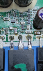
Remove IC305 and confirm that the IC is shorted and not the pads.
After it's out of the circuit, re-check the resistance from pin 5-8 on IC301.
After it's out of the circuit, re-check the resistance from pin 5-8 on IC301.
Wow, that was a challenge, they are also glued underneath.
This is the readings:
*Chip (ic305) OUT of the board reads:
between pin 5 and 6 = 3.5k ohm
between pin 5 and 7 = OL
between pin 5 and 8 = 1.7k ohm
ic305- pads:
between pin 5 and 6 = 0 ohms (there is a trace between them)
between pin 5 and 7 = OL (one way) 500k (the other way)
between pin 5 and 8 = 1 ohm
ic301- chip on board:
between 5 and 6 = 0 ohm (trace between them as well)
between pin 5 and 7 = 555k ohm
between pin 5 and 8 = 1 ohm
This may be an LM211 (suggested on a different forum and may have been staring us in the face all along).
What waveforms do you have on the other IC?
What waveforms do you have on the other IC?
Should i put it back first before i power the amp?
Before i took it off i had no waves of any kind on the the one like this (ic301)
Before i took it off i had no waves of any kind on the the one like this (ic301)
ICs like the 4093 (logic ICs) aren't likely to be drivers. They're often used to either square up a waveform or to help in building deadtime (with parallel RC networks).
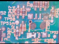
If you follow the gate drive back away from the outputs, you will likely find transistors. They may be the only drivers. The ICs farther back in the circuit may only do light duty (not driving the outputs like other 'driver' ICs... 21844, 2113...).
If you follow the gate drive back away from the outputs, you will likely find transistors. They may be the only drivers. The ICs farther back in the circuit may only do light duty (not driving the outputs like other 'driver' ICs... 21844, 2113...).
That must be how its driven,(every output fet has it's own circuitry just below it with 350 thousand transistors 🙂, I accept Defeat (for now at least)
I really appreciate all the effort Perry, just gonna put it aside for now, and come back to it years later, or start using it for parts.
The end.
I really appreciate all the effort Perry, just gonna put it aside for now, and come back to it years later, or start using it for parts.
The end.
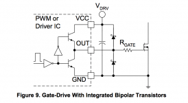
The End My Rear, im not a quitter, this looks to be how they are driven,(well with a few added transistors and bits and bobs , alpine lol) but not sure,
in this diagram they are showing a square wave on the LHS before the diode, does that mean there is a driver IC generating that outside the diagram? (cause im looking at the wrong schematic if thats right)
just trying to understand the circuitry behind this amp, then it will all become clear.
in this diagram they are showing a square wave on the LHS before the diode, does that mean there is a driver IC generating that outside the diagram? (cause im looking at the wrong schematic if thats right)
just trying to understand the circuitry behind this amp, then it will all become clear.
Attachments
- Home
- General Interest
- Car Audio
- Alpine MRP-M2000 repair project