This probe only goes up to 5V/div so I'd have to shift the zero position. I'll need to see if I can find my other probes as the tek P6137 probes I have seem to behave oddly on the 2246. (probably because they are for my 2432)
The power supply section of the schematic from the service manual. They sit in the middle of the inverters. (section labelled as CANCEL)
The power supply section of the schematic from the service manual. They sit in the middle of the inverters. (section labelled as CANCEL)
An externally hosted image should be here but it was not working when we last tested it.
Shifting the reference to a different point is OK as long as the refe4rence is stated.
You need to calibrate the probes when moving from one scope to another.
You need to calibrate the probes when moving from one scope to another.
Some of the earlier images made it appear that deadtime could be a problem. If you have a 1k (up to 4.7k likely OK) resistor and a diode (1n4148, 1n400x...). Connect the diode between pins 3 and 7 (cathode on 7) and the resistor between 3 and 14. That should give approximately 1/2v on pin 3. If you get the 1/2v, does that decrease the idle current draw?
I will need to have a dig through my component boxes but I imagine I should have the necessary parts to try this. These are the pins on the 494?
I've calibrated the probe with x10 on so I could get the whole vertical trace to fit.
Q710 - low current draw (Q709 matching transistor from other side of inverter behaves identically) This is from ch1-4 supply.
Q710 - current limit
Q711 - low current draw (doesn't behave identically to twin for the other half) Ch5/6 psu
Q711 - current limit
Q712 - low current draw (this along with Q711 are original and survived the psu failure)
Q712 - current limit
Inverters.
Q722 - low current draw (all 6 inverters from both halves behave identically) Ch1-4
Q722 - current limit
Q725 - low current draw (one half behaves differently to the other) Ch5/6
Q725 - current limit
Q724 - low current draw - other side of the inverter for Ch5/6. Oddly Q716 doesn't show the notch out of the square wave like the other two
Q724 - current limit
I've calibrated the probe with x10 on so I could get the whole vertical trace to fit.
Q710 - low current draw (Q709 matching transistor from other side of inverter behaves identically) This is from ch1-4 supply.
An externally hosted image should be here but it was not working when we last tested it.
Q710 - current limit
An externally hosted image should be here but it was not working when we last tested it.
Q711 - low current draw (doesn't behave identically to twin for the other half) Ch5/6 psu
An externally hosted image should be here but it was not working when we last tested it.
Q711 - current limit
An externally hosted image should be here but it was not working when we last tested it.
Q712 - low current draw (this along with Q711 are original and survived the psu failure)
An externally hosted image should be here but it was not working when we last tested it.
Q712 - current limit
An externally hosted image should be here but it was not working when we last tested it.
Inverters.
Q722 - low current draw (all 6 inverters from both halves behave identically) Ch1-4
An externally hosted image should be here but it was not working when we last tested it.
Q722 - current limit
An externally hosted image should be here but it was not working when we last tested it.
Q725 - low current draw (one half behaves differently to the other) Ch5/6
An externally hosted image should be here but it was not working when we last tested it.
Q725 - current limit
An externally hosted image should be here but it was not working when we last tested it.
Q724 - low current draw - other side of the inverter for Ch5/6. Oddly Q716 doesn't show the notch out of the square wave like the other two
An externally hosted image should be here but it was not working when we last tested it.
Q724 - current limit
An externally hosted image should be here but it was not working when we last tested it.
That's just my wording. Essentially I meant the photo shows the waveform before the current draw starts to rise rapidly. (I've taken it a split second after turning the remote on.)
The image below "Q724 - low current draw" shows a waveform with only 0.6 amps of current draw. Why do others show 6+ amps of draw?
Probably means I was very quick taking that photo after plugging the remote in. I took two shots of every waveform for each transistor. One within a second of switch on with a sub 2A draw showing the initial waveform and the other just at the point where the current limiter kicks in around 6-7A. I did this to try to show how it changes.
Got a 1n4001 diode and a 1.5k 1/4W carbon film so I'll give your mod a go now.
Looks correct?
Looks correct?
An externally hosted image should be here but it was not working when we last tested it.
Last edited:
No shorts. I've tested it with the mod in place and current draw still hits the full 10A limit of my supply.
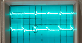
Before the current limiter is hit and the voltage falls, there is virtually no overlap.
Once the current limiter is hit and the voltage drops below about 9V, the overlap reappears as before.
I've used my other scope so that I could use the two matching probes as they behave properly on this one.
An externally hosted image should be here but it was not working when we last tested it.
Once the current limiter is hit and the voltage drops below about 9V, the overlap reappears as before.
An externally hosted image should be here but it was not working when we last tested it.
I've used my other scope so that I could use the two matching probes as they behave properly on this one.
I would have expected 1/2v on pin 3 to make more of a difference.
Try pulling pins 9 and 10 down with resistors connected to pin 7. Anything between 100 and 330 ohms should help. 220 ohms preferred.
Try pulling pins 9 and 10 down with resistors connected to pin 7. Anything between 100 and 330 ohms should help. 220 ohms preferred.
I don't think there is going to be sufficient room around the legs of the IC to squeeze another two 1/4W resistors in.
Is this mod trying to prove that there is a problem external to the IC or internal?
Is this mod trying to prove that there is a problem external to the IC or internal?
You can stand the resistors on end. You can remove the diode and the other resistor if they made no difference.
The 494 has no real ability to pull the voltage down. Pulldown resistors are used on the outputs of the IC to help prevent overlap. Alpine used resistors as low as 100 ohms. Most of the time, the resistance is 220-1k ohms. I generally use 220-330 ohms.
The 494 has no real ability to pull the voltage down. Pulldown resistors are used on the outputs of the IC to help prevent overlap. Alpine used resistors as low as 100 ohms. Most of the time, the resistance is 220-1k ohms. I generally use 220-330 ohms.
- Status
- Not open for further replies.
- Home
- General Interest
- Car Audio
- Alpine 3566 issue