Ok, so rather than measuring the voltage across the emitters of the pair I need to measure across each emitter to ground? (following page 25/26 in the service manual?)
Measuring to ground is not as simple because you have DC offset on each channel and that skews the readings. Measuring emitter to emitter is more accurate.
IF there are no bias pots, you may have to change the value of some of the components to get the bias back as it should be.
IF there are no bias pots, you may have to change the value of some of the components to get the bias back as it should be.
The service manual says that the emitter voltage on each output should be +/- 0.01V depending on which half is being measured. If that is correct, should my measurements show 0.02V (200mV ?) Seems rather high vs the 2mV suggested earlier.
There are definitely no trim pots in this amp to set anything. Something either I've done or as a result of the psu failure has caused this. I've checked all of the capacitors for backwards fitting but all are in correctly.
There are definitely no trim pots in this amp to set anything. Something either I've done or as a result of the psu failure has caused this. I've checked all of the capacitors for backwards fitting but all are in correctly.
0.01 is 10mv. With 10mv across the emitter resistors, the idle current will be very high. 10 amps may be normal.
If you want to try to reduce the bias current temporarily, you can reduce the value of the resistor that's connected between the base and collector of the bias transistor. Connecting a second resistor in parallel with the resistor that's there will work for testing. If the resistor is a 4.7k, you may want to try a 10k or 20k in parallel.
Measure the voltage across the emitters to get an initial reading and then measure again to confirm that you're moving in the right direction (lower voltage).
Hmm, that can't be right though as it shouldn't be that high. Based on this thread, the idle should be around 3.5-4A. What are the likely causes for high current draw? Driver IC's?
My values above in mV are still wrong so I'll rewrite them in Volts as they were displayed on the meter. (my head just isn't working properly this week, I attribute that to spending too much time in work)
DC voltage across the emitters of the output transistors here are the results:
Q604/605 - 0.0020V
Q204/205 - 0.0017V
Q404/405 - 0.0018V
Q304/305 - 0.0021V
Q104/105 - 0.0018V
Q504/505 - 0.0021V
These are the peaks before the limiter is hit:
Q604/605 - 0.0025V
Q204/205 - 0.0036V
Q404/405 - 0.0033V
Q304/305 - 0.0041V
Q104/105 - 0.0037V
Q504/505 - 0.0022V
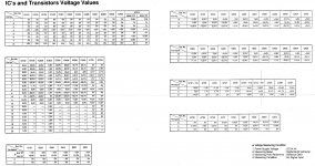
This is the page from the service manual with all of the IC and transistor voltages. (x04 & x05 are the main outputs, x02 are the bias transistors)

My values above in mV are still wrong so I'll rewrite them in Volts as they were displayed on the meter. (my head just isn't working properly this week, I attribute that to spending too much time in work)
DC voltage across the emitters of the output transistors here are the results:
Q604/605 - 0.0020V
Q204/205 - 0.0017V
Q404/405 - 0.0018V
Q304/305 - 0.0021V
Q104/105 - 0.0018V
Q504/505 - 0.0021V
These are the peaks before the limiter is hit:
Q604/605 - 0.0025V
Q204/205 - 0.0036V
Q404/405 - 0.0033V
Q304/305 - 0.0041V
Q104/105 - 0.0037V
Q504/505 - 0.0022V
This is the page from the service manual with all of the IC and transistor voltages. (x04 & x05 are the main outputs, x02 are the bias transistors)
Attachments
Will it idle with the limiter set to 5 amps?
If so, let it idle for a few minutes to see what starts to heat up. Everything needs to be tightly clamped to the heatsink.
If so, let it idle for a few minutes to see what starts to heat up. Everything needs to be tightly clamped to the heatsink.
Not sure whether it will or not. The inverters start to squeal very loudly after a 10-15 seconds. Longest I've left it on via the remote is about 25 seconds. None of the outputs or power supply parts got warm in that time.
Last edited:
I think you're going to have to decide what to do next. It's old and the power supply transistors are fragile and powering it directly could cause more damage. If it was my amp, I'd use a 10 amp fuse to power it with no other current limiting and see what happens... but it's not mine and you'll have to decide what to do.
There are other options like disconnecting the rectifiers for one supply at a time to see if either half of the amp will power up on its own.
If the fuses aren't all in parallel, you could pull the fuses for one supply then the other to see if either will power up. This would require that each half had its own driver IC for the power supply.
Fuses are in parallel, but pulling the two rectifying diodes out would work. Not a bad idea at all. I would hope that would at least help me to pin point which section has the issue.
Tried the amp with D713 & D714 removed and current draw is still too high. (hit 8.5A limit) Retried with D711 & D712 removed too, meaning no rectifiers at all and the current draw hit the limiter again. I think that isolates the problem to the power supply. The two halves of the inverter for ch5/6 aren't new but tested good which makes me wonder about it. (plus the halves are not matching batch codes) My supplier of 2SD1669's only had 4 and I had 1 new one floating about. (these are also not matching batches) Unless I can find where I've put my old 3552, I don't have a 6th one. (should be 6 brand new matching ones in it)
Any other ideas on the likely cause?
Any other ideas on the likely cause?
Last edited:
What frequency is the power supply operating at?
Check on pin 9 or 10 of the TL494 driver IC (if that's what they're using).
Check on pin 9 or 10 of the TL494 driver IC (if that's what they're using).
Yes it's an NEC variant of the 494. Here is the scope trace from pin 9. Pin 10 is the same frequency and voltage. When the current limiter is hit, the output voltage on these pins falls, but frequency and waveform shape remain pretty much as is.
I believe 40us is 25KHz
I believe 40us is 25KHz
An externally hosted image should be here but it was not working when we last tested it.
Some better images. (settings the same as above, AC coupled isn't showing as lit as the shutter speed was too high) The "on" duration increases as current draw rises and voltage falls. CT is 1.2nF and RT is 18K. (based on the datasheet formula for push pull operation, I calculated roughly 27KHz based on the values for CT & RT)
Pin 9 just as it hit the current limiter.
Pin 10 as above.
Pin 5
A ripple forms as current draw rises.
Current limiter hit
Pin 9 just as it hit the current limiter.
An externally hosted image should be here but it was not working when we last tested it.
Pin 10 as above.
An externally hosted image should be here but it was not working when we last tested it.
Pin 5
An externally hosted image should be here but it was not working when we last tested it.
A ripple forms as current draw rises.
An externally hosted image should be here but it was not working when we last tested it.
Current limiter hit
An externally hosted image should be here but it was not working when we last tested it.
Last edited:
If you had the scope properly set up with the trace on the center reference, you have a problem with the ground for the IC.
EDIT:
I see the scope is set to AC coupling so it was not properly set up.
25kHz is OK.
EDIT:
I see the scope is set to AC coupling so it was not properly set up.
25kHz is OK.
Last edited:
Good to hear 25KHz is OK. I've redone the measurements with the scope both zeroed to ground and DC coupled just to be sure. (I did forget to shut off ch2 when doing single channel measurements) I've let it run for longer and so far no disasters and no awful screeching. T703 gets warmer than T704 but certainly not hot. The heatsink gets warm but no individual inverters seem to get any warmer than the rest.
Pin 9 Peak +ve voltage.

Pin 5 Peak +ve voltage

Pins 9 + 10 together pre current limit

Pins 9 + 10 together post current limit (lowered to 2V/div)

Pin 9 Peak +ve voltage.
Pin 5 Peak +ve voltage
Pins 9 + 10 together pre current limit
Pins 9 + 10 together post current limit (lowered to 2V/div)
Last edited:
Are you getting any large spikes/ringing on the collectors of the power supply transistors?
On the pin9/10 image at 2v, it looks like you may have a deadtime issue. Severe ringing may indicate that there is some overlap.
On the pin9/10 image at 2v, it looks like you may have a deadtime issue. Severe ringing may indicate that there is some overlap.
I'm virtually unable to determine a waveform from the collectors of the inverters once the remote is switched on. It becomes almost a solid lump of green with defined top and bottom lines. With the amp off, I get 13V DC on the collectors of all the heatsinked transistors in the power supply.
Any ideal settings I should be using? (presently 5V/div, 20us/div DC coupling)
Any ideal settings I should be using? (presently 5V/div, 20us/div DC coupling)
Try changing the trigger level and the trigger coupling. That scope should easily trigger on that signal.
Looks like the probe was playing up. Used another and got something more meaningful. Other transistors of same type within the circuit seem to measure similarly.
Q710 Collector (2SC4024)
Q715 Collector (2SD1669 inverter)
Q710 Collector (2SC4024)
An externally hosted image should be here but it was not working when we last tested it.
Q715 Collector (2SD1669 inverter)
An externally hosted image should be here but it was not working when we last tested it.
An externally hosted image should be here but it was not working when we last tested it.
When posting waveform photos, set the vertical amplifier to allow the entire waveform to be seen. The top of the waveform is important. Also set the timebase to show approximately 3-4 full cycles.
I don't know how the 4024 is being used so I don't know what to make of the waveform.
I don't know how the 4024 is being used so I don't know what to make of the waveform.
- Status
- Not open for further replies.
- Home
- General Interest
- Car Audio
- Alpine 3566 issue