Hello,
I have an Alpine 3544 and is has very high dc offset, on the left chanel i measured 80mV, on the right channel 180mV and bridged output 60mV.
Im using a 22 amp pc powersupply to power the amp.
I'm new to electronics and i would like to learn how to fix it.
When i got the amp i replaced the 1000 uF filter capacitor
If you need more info i can do some more measurements.
Thanks in advance.
Best regards,
Wessel
I don't normally dip into the car audio stuff but suspect that what you are seeing is probably normal. Also, Class D amps carry a lot of hf artifacts and these can give misleading readings on a dvm. You could try a 10k and 1uf cap in series and place that combination across where you are trying to measure the offset. Read the voltage across the cap for a truer reading with all the noise filtered out.
With the black meter probe on the left negative speaker terminal, what is the DC voltage on pins 4 and 5 of IC501 and IC502?
@Mooly
the 3544 isn't a class D amp is it?
Would the pc powersupply be the cause of the offset?
I also have a car battery laying around, i will hook it up and test again.
@Perry
Are IC 501 and 502 the IC's near the gain potentiometer?
the 3544 isn't a class D amp is it?
Would the pc powersupply be the cause of the offset?
I also have a car battery laying around, i will hook it up and test again.
@Perry
Are IC 501 and 502 the IC's near the gain potentiometer?
So the fourth and fifth pin from the left side of both heatsinked IC's?
Which one is 501 and 502 i don't think they are marked.
Which one is 501 and 502 i don't think they are marked.
Yes. Be careful not to let the probe short to the longer legs when measuring the voltage on the legs directly under the IC.
501 is the one nearest to the cable that comes from the RCA connector board.
501 is the one nearest to the cable that comes from the RCA connector board.
On IC 501 the voltage on pin 4 is also 0V.
But when I measure the voltage on IC 502 pin 4 something starts to hum rather badly and I switched my powersupply off, it could be the amp humming or the powersupply.
But when I measure the voltage on IC 502 pin 4 something starts to hum rather badly and I switched my powersupply off, it could be the amp humming or the powersupply.
I'm not sure if my meter can do that but what caused that hum you think?
My meter is a Ferm MM-960 it's a common brand in The Netherlands.
It's a cheap meter but it's not crap.
I will try to do some more measurements.
My meter is a Ferm MM-960 it's a common brand in The Netherlands.
It's a cheap meter but it's not crap.
I will try to do some more measurements.
I don't know what caused the hum.
You already posted voltages with that resolution. 80mv is 0.080v.
You already posted voltages with that resolution. 80mv is 0.080v.
You are right, dumbass me 🙁
I'm a little busy at work atm I hope I can de the measurements tomorrow.
I'm a little busy at work atm I hope I can de the measurements tomorrow.
Ok, got it!
501
-pin 4: 0,5mV
-pin 5: 0,4mV
502
-pin 4: -2,5mV
-pin 5: 0,7mV
I tested another car amp i have, an Alpine v12 mrv-f300s.
It had a maximum offset of 10 mV!
Merry Christmas to you all!
501
-pin 4: 0,5mV
-pin 5: 0,4mV
502
-pin 4: -2,5mV
-pin 5: 0,7mV
I tested another car amp i have, an Alpine v12 mrv-f300s.
It had a maximum offset of 10 mV!
Merry Christmas to you all!
IC502 appears to be defective, especially if it produces clean power up to clipping (at the same point as the other channel) when driving a load.
If you want to confirm, you could swap IC501 and 502 to see if the offset follows the IC or remains in the right channel.
If you want to confirm, you could swap IC501 and 502 to see if the offset follows the IC or remains in the right channel.
Well there is offset on both channels but the right channel is the worst.
Should I swap both IC's and see if the left channels gets the higher distortion?
How do I remove the board out of its casing? Do I have to unscrew all transistors?
And is it possilble to remove the IC's using a normal soldering iron because I dont have a desoldering iron?
Do you think the offset will be gone by only replacing those IC's?
Thanks once again!
You shouldn't attempt this without the right tools.
Is one channel distorted? I thought the problem was only offset.
If you do remove the board, you have to remove any screws holding the board and also remove the screws holding the aluminum plates that the transistors are mounted on.
I wanted you to swap the ICs to see if the higher offset followed one of the ICs. If so, you'd know (fairly definitively) that the problem was due to a defect in the IC and not something else. If the high DC offset remained after swapping the ICs, then the problem would likely be in the other components in the channel.
Of course, this is assuming that both channels produce clean audio and the only complaint is offset.
Sorry, no distortion only offset!
The amplifier had another problem when it arrived, I turned it on and it went into protection mode.
My 30A!! powersupply also shut down because it overloaded or shorted (i think overloaded but not 100% sure)
After turning it on and off a couple times it stayed on.
After looking at the upc1298v amplifier driver IC it all makes sense.
The driver IC also 'manages' the protection mode.
When I got the amp I replaced the filter capacitor because it leaked.
Maybe the IC's got damaged because of the unfiltered power.
Thats my nooby theory😀
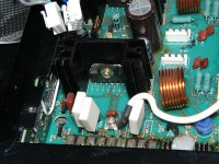
I have attached an image because i have no idea how to remove the heatsinks, the hole in the picture is definitely no screw.😕
http://www.littlediode.com/datasheets/pdf/Datasheets-UPC/UPC1298V.PDF
The amplifier had another problem when it arrived, I turned it on and it went into protection mode.
My 30A!! powersupply also shut down because it overloaded or shorted (i think overloaded but not 100% sure)
After turning it on and off a couple times it stayed on.
After looking at the upc1298v amplifier driver IC it all makes sense.
The driver IC also 'manages' the protection mode.
When I got the amp I replaced the filter capacitor because it leaked.
Maybe the IC's got damaged because of the unfiltered power.
Thats my nooby theory😀
I have attached an image because i have no idea how to remove the heatsinks, the hole in the picture is definitely no screw.😕
http://www.littlediode.com/datasheets/pdf/Datasheets-UPC/UPC1298V.PDF
Attachments
Last edited:
Old electrolytic capacitors tend to become leaky (electrically) if they're not used for a long period of time. When you initially applied power, the leakage may have been excessive. After having power applied for a while, the capacitors may have 'reformed' (rebuilt the insulative coating on the plates) which would have eliminated most of the leakage.
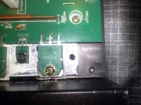
Most alpine amps have aluminum plates that the transistors are mounted on and the plates come out of the amps with all transistors still attached (see image below as one example). In this amp, it appears that they machined away all but the area that needed to be raised, which would mean that all of the screws holding the transistors down would need to be removed.
The ICs drift with time. There isn't necessarily a reason for them to have excessive offset.
Attachments

- Status
- Not open for further replies.
- Home
- General Interest
- Car Audio
- Alpine 3544 dc offset