Do you think the 8r version is ok for this.
https://www.diyaudio.com/community/attachments/2023-07-20-2-png.1195015/
Sorry that didn't attach how I imagined!
https://www.diyaudio.com/community/attachments/2023-07-20-2-png.1195015/
Sorry that didn't attach how I imagined!
I forget what the part number is - there is a schematic in post #961, also below. It is a basic 15v Zener in SMT format. I think this one should work, 5.2mm L x 2.5mm dia. Note that the polarity of the diode is different for N vs P channel MOSFETs.Can anyone please inform me about the part number ( Mouser please) of the 15V zener for the snubber board?
Thanks a lot
https://www.mouser.com/ProductDetail/Vishay-Semiconductors/ZM4744A-GS08?qs=TNTIDjy6APo/9u5wXpJZkg==
Last edited:
Thank you very much. I checked your mouser BOM and i found what you had recommended at post#1.

Hola, mi opinión es que no. La impedancia mínima es de 5 ohmios y en un lugar (por encima de 100 Hz) donde el amplificador tendrá que suministrar energía. Debes buscar una carga que no baje de los 6 ohmios. Un verdadero altavoz de 8 ohmios no debe bajar de los 6,4 ohmios.¿Crees que la versión 8r está bien para esto?
https://www.diyaudio.com/community/attachments/2023-07-20-2-png.1195015/
¡Siento que no se haya adjuntado como me lo imaginaba!
Saludos cordiales
Hello, my opinion is no. The minimum impedance is 5 ohms and in a place (above 100hz) where the amplifier will need to deliver power. You should look for a load that does not go below 6 ohms. A true 8 ohms speaker should not go below 6.4 ohms.
Best regards
Best regards
Sorry, that's the thing about writing in another language, in the end you make little messes 😉
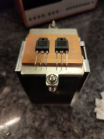
Got the new sinks. Decent sized things. Fans are 80mm and have a 5 wire pwm connection, albeit the outer two (black) are linked. Don't know if this is compatible with the fan modules mentioned in this thread?!
Quite a weight to them so I'm hopeful they are suitable for some of my class a projects.
Quite a weight to them so I'm hopeful they are suitable for some of my class a projects.
Attachments
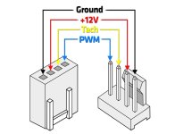
Most PWM fans are 3 wire. 5 wire might be proprietary or have a speed sensor?
This is and example of the standard PWM controller. The Noctua fans are compatible. This will handle 4 fans.
https://a.aliexpress.com/_msFoBnk
This is and example of the standard PWM controller. The Noctua fans are compatible. This will handle 4 fans.
https://a.aliexpress.com/_msFoBnk
I think you're right X. The fans have 5 wires with a commoned ground next to the blue. I found this good bit of info.
Post #4 if not direct to it.
https://forums.tomshardware.com/thr...2-pin-vs-3-pin-vs-4-pin.2200004/post-14732311
Post #4 if not direct to it.
https://forums.tomshardware.com/thr...2-pin-vs-3-pin-vs-4-pin.2200004/post-14732311
Attachments
Last edited:
Waiting for my pcbs to arrive from etsy ( I have heard some rumors for a worldwide tour before arriving ), I decided to play with my favorite layout 6 dealing with the designer's wonderful pcb ( It's a design over the original prototype ).
And here it comes the Alpha Nirvana 4R with all the values of the spare parts, no smd parts (I am old fashioned), no molex, according to my personal taste.
If anyone want the gerber files, i will send them in pm.
Your opinions would be more than welcome.

And here it comes the Alpha Nirvana 4R with all the values of the spare parts, no smd parts (I am old fashioned), no molex, according to my personal taste.
If anyone want the gerber files, i will send them in pm.
Your opinions would be more than welcome.
Nice work! If I may ask you to please attribute the amp design to Hugh Dean on the silkscreen, that would be nice and indicate that the layout is by yourself so people don’t confuse this with the “official” Alpha Nirvana PCBs which are fully tested and verified. Thanks.
For avoiding any further misuderstanding, I think I was very clear about that design. It is not the original-official Alpha Nirvana pcb. The layout 6 users can easily uderstood how i have made it. Open sprint lay out. press extras and click scanned copy. You insert the image( ie AN ) and add traces, parts etc while you make all your different changes to the copy. This specific design has no commercial purposes. Is it clear now? If somebody wants the gerbers. they are available to whom it may concerns! It can't be clearer!!!!!
It is like an offer to diyaudio community . I have made that pcb so that when XRK pcbs arrive ( I hope soon ) not to deal with Andy's BOM, 8R and 4R schematics. Thus my bench will be free of unecessary documents.That's all!!
It is like an offer to diyaudio community . I have made that pcb so that when XRK pcbs arrive ( I hope soon ) not to deal with Andy's BOM, 8R and 4R schematics. Thus my bench will be free of unecessary documents.That's all!!
That's more than a clear answer.
I have made that pcb so that when XRK pcbs arrive ( I hope soon ) not to deal with Andy's BOM, 8R and 4R schematics. Thus my bench will be free of unnecessary documents.
If there were any other purposes why should I publish it? The pcb photo is intentionally taken in layout 6 photo view.
If the designers are offended by my personal work, I will surely and definitely delete it at once. I want to declare that I am not a seller of anything. I am an experienced technician electronic who is a hobbyist too ( I design tube preamplifiers for my own use ).
Not offended at all. I think you did a great job - I never said we were not happy. It’s just common courtesy and accepted practice on DIYA to cite the name of the circuit designer when posting a DIY design online.That's more than a clear answer.
I have made that pcb so that when XRK pcbs arrive ( I hope soon ) not to deal with Andy's BOM, 8R and 4R schematics. Thus my bench will be free of unnecessary documents.
If there were any other purposes why should I publish it? The pcb photo is intentionally taken in layout 6 photo view.
If the designers are offended by my personal work, I will surely and definitely delete it at once. I want to declare that I am not a seller of anything. I am an experienced technician electronic who is a hobbyist too ( I design tube preamplifiers for my own use ).
Take as an example, the FH9 amp layout by member Sonal, he credits Apex and xrk for the mod of converting the FX8 to FH9. He puts his own name for the layout.
So I am just asking you add this to silkscreen Gerber: “Circuit by Hugh Dean”
- Home
- Amplifiers
- Solid State
- Alpha Nirvana 39w 8ohm Class A Amp