Patrick, I wish you well in your all Fet design/testing, but there might be hurdles due to the fact that many of the small signal fets in the published design are not available and subs will need to be considered carefully
We planned to build this as published long ago, for our own curiosity.
The PCB was designed in early October.
It has been on the to -do list since.
And we shall publish only when fully tested and independently auditioned, as we always do.
Irrespective of whether there is interest for a GB or not.
We actually have all the original transistors for the BJT version, from our Le Monstre 2024 project.
But it is, for us, not interesting enough.
As to parts substitution, as we have proven with proper ABx test in our Le Monstre 2024, the insistence on using original parts is overrated, to say the least.
Of course you need to know how, without saying.
Merry Christmas,
Patrick

@wahab
Hi Wahab:
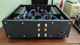
I assembled the boards inside the cabinet as in the enclosed picture.
As I had stated, everything worked just perfect outside. But now I have problems.
I think it is oscillating again. When the volume control is suddenly increased or increased, it is drawing high current.
There is another peculiar problem. If I quickly change the volume (low to high or high to low) upto 35v DC is appearing at the speaker terminals for a second. And then it is back to zero.
Kindly suggest what to do.
Please don't mind for the wire jumble. I shall clean it up later.
Ganesh Laxmanmurthy
Hi Wahab:
I assembled the boards inside the cabinet as in the enclosed picture.
As I had stated, everything worked just perfect outside. But now I have problems.
I think it is oscillating again. When the volume control is suddenly increased or increased, it is drawing high current.
There is another peculiar problem. If I quickly change the volume (low to high or high to low) upto 35v DC is appearing at the speaker terminals for a second. And then it is back to zero.
Kindly suggest what to do.
Please don't mind for the wire jumble. I shall clean it up later.
Ganesh Laxmanmurthy
Attachments
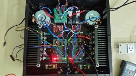
First thing to check is that the speaker ground on the output connector goes directly to the power supply
star ground, it shouldnt be taken on the amp s board.
Since you have two PSUs each speaker ground is taken at its relevant star ground.
Other than this you can try a 100-220pF cap connected from amp input and ground, eventualy it can be connected
directly on the potentiometer if the potentiomer to amp cables are not long.
Also what is the source you are using and what is the value of he potentiometer.?.
Last edited:
A photo of a 20KHz square wave would be useful (make sure your sig gen makes a nice, clean square in the first place - and that your probes are calibrated).
Hi Wahab:
I think I solved the issue. Bu mistake, I had connected the signal ground to the star ground. Once I disconnected it, it is working perfectly.
Below is how I have built it.
I have tried to keep both the channels discrete.
Power Supply:
Mains Supply -> RFI-EMI Filter -> DC Scraper -> Soft Starter -> Power Transformer -> PSU -> Amplifier
Amplifier Output -> Speaker protection -> Speaker Terminals
Chassis is Earth and I have added Ground-Loop-Breaker.
Volume control is high quality 47K LOG potentiometer.
Kindly suggest if any changes are required.
I shall cleanup the mess and update with the pictures.
Sound quality is impeccable. Absolutely no hiss, hum or noise being picked up from any source.
Ganesh Laxmanmurthy
@thermionic
Thank you for information. I think the problem is resolved. I shall do more testing in a day and update.
@hbtaudio
Thank you. True. This is the best ever amplifier that I have built. I was planning on F5 turbo V2 or V3. I had procured all the components. Now I think it is not required. Also I have six other amplifiers (all DIY - starting with Elector Electronics Crescendo made in 1992 when I was 1st year engineering student). Now I don't know what to do with them.
Ganesh
@lganimys, very nice build of yours, that look way better than a ton of semi industrial amps l ve seen
through the years, hope it will give you satisfaction for the years to come, and in this respect i ll add a remark.
Your heatsinks are beefy but in a closed case the heat will slowly build up given that the max dissipation is about 60W/channel
in the most unfavourable case, wich is precisely about 2 x 60W RMS continuously with no variation at all, wich i admit will hardly happen in real usage but if used as PA amp it could get close.
If ou intend to do so then add two small fans just in the vents near the transfos to extract the air and push it out of the case,
two small 5 x 5cm or 6 x 6cm fans, if they can be found with 24V models, connected in serial with two 80°C parraleled
thermo contacts, each one fixed on a side of the heatsinks, and the whole supplied by a +50V rail, so both fans are switched on
once one channel s heatsink hit 80°C, lower thermals increase much the lifecycle of the electrochemical capacitors as well
as the long term reliability in case of PA like usage.
@mlloyd1 @wahab @gaborbela
I tested the amplifier for continuous 4 hours. Everything just works fine. The original circuit also works just fine. I tested that in the final run.
So, this amplifier works out-of-the-box. No need for any changes.
Tomorrow I shall post the final pictures.
Wahab, Since it is for home listening, I don't think we need fans to cool it. I hate fans because that itself will add some db of noise. In fact that will be a negative to this dead silent amplifier. The base of the heatsink itself is 15mm and the blade length is almost 70mm. So the surface area for heat dissipation is very large. Also since the heatsink is mounted on the chassis floor, the cabinet itself absorbs some heat and radiates outside. Even with reasonable volume, the heatsinks are just getting warm.
Ganesh
@lganimys, for home use that s indeed perfect, let us see what the final build look like, and also, do you mean that you tested back the original schematic with the 47pF + 220pF previous compensation.?
And for what gain did you settle as definitive value.?.
@mlloyd1 @gary s , we ll have to wait that lganimys give us more precisions about his final values, i ll update the schematic accordingly, lately the compensation was increased from the mentioned values to 68pF + 330pF, that s actually the only real change, also after he got it stable on his second test once cased he eventualy increased the gain.
Last edited:
Hi
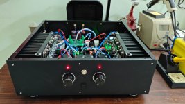
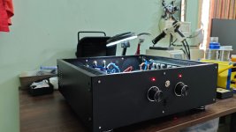
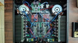
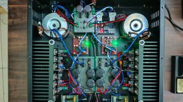
I have attached a few pictures of the amplifier. From the top view except the RFI-EMI filter, all the other modules are visible. RFI-EMI filter sits below the DC scraper module.
Stereo separation is on par with any audiophile amplifier.
The sound from both the channels are identical. To achieve this, every component has been measured for precision. Components with exact measured values are sitting in both the channels.
All transistors in the input, VAS and driver stages have been measured for near identical Vbe in respective channels. I fact I have kept the lengths of all the wires in both the channels equal.(a bit too much)
The input sockets are of RCA type and medium quality but gold plated. The co-axial signal wire from the back panel to the front volume control is triple shielded to repel any stray noise.
I considered balanced input, but due to lack of time, I settled with RCA.
The volume controls are of Alpha make and of reasonable quality. I considered Alps, but procuring it would take time.
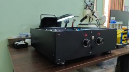
The cabinet is boring but had to settle with it because of non-availability of good ones'. Else I had to make one which is time-consuming.
If anyone has any questions, they can ask me.
Ganesh
I have attached a few pictures of the amplifier. From the top view except the RFI-EMI filter, all the other modules are visible. RFI-EMI filter sits below the DC scraper module.
Stereo separation is on par with any audiophile amplifier.
The sound from both the channels are identical. To achieve this, every component has been measured for precision. Components with exact measured values are sitting in both the channels.
All transistors in the input, VAS and driver stages have been measured for near identical Vbe in respective channels. I fact I have kept the lengths of all the wires in both the channels equal.(a bit too much)
The input sockets are of RCA type and medium quality but gold plated. The co-axial signal wire from the back panel to the front volume control is triple shielded to repel any stray noise.
I considered balanced input, but due to lack of time, I settled with RCA.
The volume controls are of Alpha make and of reasonable quality. I considered Alps, but procuring it would take time.
The cabinet is boring but had to settle with it because of non-availability of good ones'. Else I had to make one which is time-consuming.
If anyone has any questions, they can ask me.
Ganesh
Attachments

@wahab
Yes. The compensation as per the original schematic just works fine. I settled with 68pF + 330pF to be on the safer side.
I think there was ground loop problem in the initial stages of testing.
Regarding the possibility of overheating, the soft-start module that I have installed has a built-in high-temperature power cut-off. I can connect the sensors to the heatsink and enable it.
Ganesh
Last edited:
@wahab @gaborbela
Happy New Year to you, your family and friends.
With due permission, can I make a Youtube video on this amplifier - of course with due credit to all you guys and the forum.
If yes, I can allot a day from my schedule after 10th of this month for this.
Ganesh Laxmanmurthy
Happy New Year to you, your family and friends.
With due permission, can I make a Youtube video on this amplifier - of course with due credit to all you guys and the forum.
If yes, I can allot a day from my schedule after 10th of this month for this.
Ganesh Laxmanmurthy
@Iganimys, did you get your pcb done with the gerber files in post #319 of this thread? Also where there any trackwork mods - or was it OK from the start?
@lganimys , thank you and happy new year as well for you and family, and hope things will get much better for @gaborbela,
and thanks for the precisions, i ll retain your implementation for the edited schematic, can you also specify your amp s gain.?
As for the video this would be great, such laterals fets based powerfull builds are not that widespread, moreover it s a continuation of Hitachi s own amps, methink that this one would had been their next step if they had released a successor
to their 9500MK2, so myself, and certainly everyone following this thread, is curious to see the beast unveiled in all its glory.
@gary s
If I remember, Alex re-posted it or sent me the gerber files personally. It is revision 4.5 dated 28-11-2012. I have attached the files that I could find on my PC.
If I remember, Alex re-posted it or sent me the gerber files personally. It is revision 4.5 dated 28-11-2012. I have attached the files that I could find on my PC.
Attachments

- Home
- Amplifiers
- Solid State
- All Hitachi Lateral FET amplifier for DIY described by Paul Kemble