I'm liking the idea of an optomos in series with a fuse
We kind of know how bad fuses sound, but the optimos audibility, at least for me, is still unknown. Unfortunately the on-resistance values do not translate easily into audibility.
Probably a non-issue for most users, but OP mentioned using a tube-rectified LCLC filtered bias circuit, which means he actually listens to these small things.
Last edited:
The OP is using a 10R current sense resistor for each cathode already. A cautious 350V rated optomos switch only introduces a 7 ohm nominal series resistance when on (eg. LCB110 in DC only config) - which could be reduced further if that is a worry (eg. to 2 ohm for LCB127 with 250V rating).
Some care is needed with fuse selection for that application - and yes DC nominal resistance needs to be appreciated, and rated current may need to be at least 100mA to keep working resistance near 10 ohm. Whether additional cathode circuit resistances of that level, and possible time/signal-related variation, are identifiable in a technical distortion measurement would be interesting to see.
Some care is needed with fuse selection for that application - and yes DC nominal resistance needs to be appreciated, and rated current may need to be at least 100mA to keep working resistance near 10 ohm. Whether additional cathode circuit resistances of that level, and possible time/signal-related variation, are identifiable in a technical distortion measurement would be interesting to see.
Thanks to all for the invaluable input. I like the suggestion to fuse at the 0v ct rather than at the cathode... Hopefully any noise introduced has a better chance of being smoothed out. I already have fuses on the + and - mains tx secondaries.
Analog_sa, what do you mean by "We kind of know how bad fuses sound," ?
Could you en-light me/us? Thanks.
Could you en-light me/us? Thanks.
The "problem with fuses is that their resistance is not constant.
For most metals, resistance rises with temperature.
Fuses are *designed* to "melt", at some current slightly over normal max current.
So they will normally run pretty warm.
Furthermore, when put in an audio-only link (speaker fuse), the current (and heat and resistance) goes zero to max and back and the other way *twice* each cycle. Plot it out, it is classic 3rd harmonic peak-flattening. Muted by the fact that the fuse time constant is much longer than an audio cycle. But not much-much-much longer as we would like. There will be some resistance variation on bass. This variation also modulates any mid/treble riding with the bass.
SE systems with DC (tube current), the audio variation is less than in a speaker line (never goes to zero), but generally not zero.
Putting a fuse upstream of the supply capacitors exposes it to turn-on surge which will typically blow the fuse, first-time or after 10 or 100 such insults.
Again (and especially when there are coils), the off-state (blown) rating must be at least 250V (double if a choke can kick). This is a minor sin, since the fuse rating is for circuits which may have "large" current available, and tube amps generally don't. This becomes an issue for say 100W guitar amps, with 500V PTs that can dump 500++ Watts for many seconds. A 250V 0.5A fuse trying to stop BIG energy can explode and injure a human. (Yet this is often done and nobody has reported more than a cracked fuseholder.)
The other problem is that sub-Amp fuses are rarer. Also invariably made of very skinny wire, so the thermal time constant is faster.
Steve, thanks for post #36 details.
Not sure what your point 9) refers to wrt 'setting to ~500mV'?
Going the uP path, especially a type that will be available in a decade or two (I guess such as a picaxe), then makes it easy to add in all those 'nice to have' functions. From a protection perspective, the ability to rapidly de-energise the circuitry is better for parts than waiting for a fuse to blow (and then protecting circuitry from the blown fuse), and removes the complexity of those protective parts.
The ability to sequence mains AC and HT may need some care for certain amps, but does reduce mains inrush - especially for ss rectifier supplies, and does reduce over-voltage stress when using cheaper directly heated cathode diode rectifiers. There would even be ways to reduce mains load current before using the relay to turn off ac mains.
I guess even a ubiquitous 5V USB supply could be an easier path to having a uP supply, rather than going down a discrete linear power supply.
I used a tiny Atmel microprocessor to do something like this. Its main purpose was to sequence power to reduce inrush but it also watches output tube currents (comparator) and if any cross a threshold, it will power the amp down. The microprocessor is in control of SSRs on the primary sides of all power transformers.
I recently switched the amps I built like this to a bias servo for the output tubes and I am really glad I have a protection circuit in case the servo does something bad.
I recently switched the amps I built like this to a bias servo for the output tubes and I am really glad I have a protection circuit in case the servo does something bad.
I'm building a power amp using 45 valves for output, interstage transformer coupled and with grid bias (trimmer surrounded by resistors to make the trimmable range what I need). The grid bias will be fed from a separate rectifier tube and LCLC filtered.
Mega bad idea! Those small vacuum diodes will take longer than the 45 folaments to warm up, so you will likely be operating the 45s without bias for awhile. Not good for longevity, especially as these cost some serious $$$$. You don't want them poofing any sooner than can be helped. Derive your bias with solid state diodes. That way, the bias will be there when the 45s warm up.
If the grid bias fails there's obviously a risk to the output tube. I'm looking into using a relay so that if the grid bias supply fails the output tube B+ will be cut. In the example circuit that I've seen, from the grid bias supply (approx 120V) a 10k resistor connects in series with a 24v relay. The ground of output tube B+ is connected when the grid coil is energised.
I've never used a relay before - can anyone clue me into how to specify and choose one ? A 10k resistor from 120V will draw around 12mA current, so I'm looking for a relay which will energise at 12mA ? The specs I've looked at on RS or Mouser seem to specify coil voltage so I think I've misunderstood something. Or using wrong terminology.
This demands a solid state solution. Use cathode current sense resistors and a comparator. The comparator can trip a circuit that shuts down a power MOSFET source follower that can also double as an active ripple filter. If you don't want to go that route, small wattage resistors as current sense resistors can be sized to poof as fuses of last resort.
How about this one?
Tube bias control
Looks interesting, but I'm really trying to avoid SS or circuit boards at least for now.
Plus, if that board fails are we back to the same issue ? No grid bias ?
So, lots of invaluable input for which as always I'm thankful. The educational value of these forums is incredible.
My conclusions from what I've heard.
1) A relay should work, and I've learned a lot about how they work and how to specify, but there may well be downsides to using them and they should not be expected to instantaneously trip
2) a fuse in the cathode would work to protect the output valve, but it's resistance will vary with current especially if it's rating is not far above the peak current anyway, thus 3rd harmonic and possible impact on sonics
3) tube rectifier for the bias supply is a bad idea because it may leave the 45 without bias on startup (and is a point of failure for the bias)
I'm led to the view that I'll change the design to remove the rectifier tube and switch to diodes, plus I'll oversize EVERYTHING in that circuit to minimise the risk of failure.
I'll use a fuse during development, then bypass it later to hear the sound difference for myself.
I'll experiment with the relays I've ordered and come back to it when I have more experience.
Some of the options involving SS comparators look really interesting. When I have this amp built those will be options I look into, but for now I have zero experience with them. I'll come back to the forum for pointers to get me started.
Thanks all.
PRR, all good points there. Thank you.
But a fuse in the cathode side sees a constant current in in classic A/AB class. So I do not think the 3rd harmonic is an issue.
Adding a fuse on the HV CT is a good idea, but then the fuse has to be sized for all HV downstream currents. But then it's difficult to be granular enough in the choice of fuse to protect one leg of your PP amp, if a tube goes a crazy, but not enough to trigger the fuse limit: but enough to take the primary of your OT...
There is no silver bullet here. It's all about compromise.
I would not use a tube rectifier for the bias supply: I am already uncomfortable with a single SS rectifier generating the negative voltage on which the whole amp sits. If this SS diode goes banana, short or open, the result is catastrophic.
I think here I would be OK to have some ss circuitry to shut down the amp when the negative bias voltage disappears.
I believe cathode fuses are a bad idea, too much distortion. I find fuses are terrible resistors, non-linear. Also, from Audio Power Amplifier Design Handbook, 5th Ed Pg.444 {sorry to quote a solid-state reference}
"... Placing a fuse in series with the output will cause low-frequency distortion due to cyclic thermal changes in the fuse resistance. "
"...They can and should therefore be of the slow-blow type, and rated with a good safety margin, so that they are entirely reliable; a fuse operated anywhere near its nominal fusing current has a short lifetime, due to heating and oxidation of the fuse wire."
I think it's silly to monitor the bias rail with a relay. You get poor fault coverage- only of the transformer/rectifier. If the bias pot or 100uF filter cap fail etc. -the relay says all is good.
What I suggest is make a gigantic analog OR gate, sampling every cathode resistor and if any one node is high (current), then trip. It would require diodes and a long time-constant unless push-pull stages are being monitored.
If this is a purist design, a tube comparator fed by the resistors sampling the cathode-resistors. Maybe a Wheatstone bridge to lessen the parts count, covering tubes in quads.
I'm just trying to put some ideas out there.
ok.Analog_sa, what do you mean by "We kind of know how bad fuses sound," ?
Could you en-light me/us? Thanks.
sarcasm (do you know what it is?)
the whole inquire looks awkward and funny: the TS wants to stay "pure" (that was my joke about, then how can you dare to use the glass-envelope tubes? as the glass is all silicone: SiO2, check the danm high school chemistry book)) but at the same time to have the level of protection not possible to achieve (unless to not much sense extent) without use of SS components.
I think OP has 45 tubes, so if one loses bias or H-K shorts it would be good to know, very hard to notice until things are melting with so many.
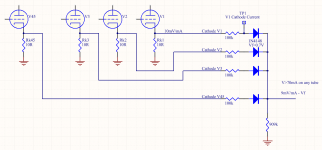
Here's a sch of what I am suggesting. Basically a summation network with diodes to make an OR function. It would lead into a comparator or meter.
With a tube-only solution , you could use passive summation (no diodes) to get the total cathode current of all 45 tubes as one voltage. Not as useful, I would rather know if one tube is cooking. Given the dollars at stake, I would have a dedicated circuit.
It's not in the signal path, just "looking" at the cathodes, so I would be ok with SS.
Attachments
I should have been a little clearer. This is a monoblock design. Each monoblock only has 1 x 5842 and 1 x 45 (plus three rectifiers).
I agree about the fuse and don't want it in the signal. However, this project is as much about learning and proving for myself what makes a real difference to the sound. I'm starting with the cathode fuse in while I test and stabilise the circuit but will bypass it in short order and listen to the difference for myself.
I plan to adopt the excellent suggestion made in an earlier post of placing a high value resistor across the trim pot. I need to draw that up and prove for myself how that will produce a high bias to close down the valve on trim pot failure.
I'm happy to use SS comparators, except that I know ZERO about using them. I'll come back to that. Just as long as they aren't in the signal path.
However, this project is as much about learning and proving for myself what makes a real difference to the sound.
Offtopic suggestion: try loading the biasing circuit down a bit. In my case it made a substantial change to the sound at the expense of more filtering. Don't really know why, perhaps at low current/voltage the rectifiers are in a bad part of the characteristic. I think they run @10mA at present. Don't save on cap quality there either, it is painfully audible.
Thanks and I agree - surely that has to be the most important circuit in the amp. The design is
Separate Mains Sec Winding 150-0-150
-> EZ81 -> 0v CT to LCLC -> Trim stack
Both caps are Mundorf Tubecap (no electrolytics anywhere in the PSU). At present I'm planning a Hammond 157G as first choke (30H 40mA) with a 20uF tubecap, followed by AudioNote Choke-180 (20H, 50mA) with a 100uF Tubecap. I suspect that Hammond might be a bad choice so at some point I'll try a better choke in there, however it's in first position so I figure there's enough smoothing after it.
Expecting around -120V across the trimmer stack. Using a 2W Allen Bradley 1k linear trim pot with 1k36 below it and 3k above, so should be able to trim between -30v and -50v. Around 20mA running through that stack, plus I'll have a bypass resistor and relay adding some current flow TBC.
- Status
- Not open for further replies.
- Home
- Amplifiers
- Tubes / Valves
- All DHT Circuit Advice