Wall Warts internally run at 100 KHz+. 😀10 W 60 Hz wall-wart transformers are smaller in size.
THX for the 'heads up' on that. I hadn't looked much at availability for some time.10Y is more common. Unlike 10, which was consumer grade tube for AC-powered radios, 10Y is designated RF. Military stocked-up on them, that's why they are relatively plentiful.
And never at 10s, never thought of building a 10 amp.
The only 10 I ever saw in action was something in the electrical/electronics shop at HS.
The 10 was run as an RF oscillator on raw AC, its own rectifier. The power system was still 25 Hz, so lots of buzzing.
It was hooked up as a Tesla coil. on the top of which was a steel phono record needle.
It supported a wire swastika of diameter of about six inches.
The swastika rotated, quite a wild & crazy display!😀
When I looked at 10 pricing the other day I experienced sticker shock! 👎
Why does no one try back biasing as in Post 25?
Common in the later 30s & solves many circuit problems.
And easy to do. 👍
Common in the later 30s & solves many circuit problems.
And easy to do. 👍
It is not good as output, too high Rp and too little power, but excellent driver. You might consider it after reading Andy's ravings.And never at 10s, never thought of building a 10 amp.
Not for folks like us on Social Security. I got my stash while I was still working. That time $25 was fair price.When I looked at 10 pricing the other day I experienced sticker shock! 👎

People do it all the time with Coleman regulators (basically current sources). But that requires separate regulator for each filament. Your approach of lighting/biasing of several tubes from a single source is great, but it has to be a voltage source, or a battery. If it is a voltage-regulated supply, that means a big electrolyte capacitor across filaments. Some believe it kills the unique sonic character of directly heated tubes.Why does no one try back biasing as in Post 25?
Common in the later 30s & solves many circuit problems.
And easy to do. 👍
Bunk!!Some believe it kills the unique sonic character of directly heated tubes.

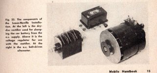
The traditional solution is a lead-acid battery. You have to recharge it with a transformer and mercury vapour rectifier every now and then.
On the subject of the 10/10Y, I tried 2 versions of the circuit - filament bias and cathode bias with DC Link bypass cap. They are both good - the cathode bias one is very refined, the filament bias one a trifle more lively. They both have marvellous tone to acoustic instruments and voices. So either way is good - the tone is equally there with both. With a 1:3 or 1:4 step-up transformer you have a great sounding 2a3 or 300b amp.
1:4 SUT (correctly loaded on secondary) + 10Y VAS stage overall gain only 25-27 (depending of 10Y loading), so it's enough only if 300B grid bias voltage is on the lower side.
If you have enough source voltage (more than 2VRMS -2.828V peek-, up to 3..3.5VRMS) the 1:4 SUT + 10Y/801 produces enough swing (with overhead) to drive 300B (up to A1).
If you have enough source voltage (more than 2VRMS -2.828V peek-, up to 3..3.5VRMS) the 1:4 SUT + 10Y/801 produces enough swing (with overhead) to drive 300B (up to A1).
1:4 SUT (correctly loaded on secondary) + 10Y VAS stage overall gain only 25-27 (depending of 10Y loading), so it's enough only if 300B grid bias voltage is on the lower side. If you have enough source voltage (more than 2VRMS -2.828V peek-, up to 3..3.5VRMS) the 1:4 SUT + 10Y/801 produces enough swing (with overhead) to drive 300B (up to A1).
This is a pretty good formula for an amp. The driver DHT could be 10Y, 26, 2P29L, 4P1L, 112A etc with various plate resistances. They all have a gain of around 8-9. Quite a few SUTs can do 1:4 so some choice there. It's a very buildable amp.
You should try the third version: battery bias with no resistors in cathode circuit.On the subject of the 10/10Y, I tried 2 versions of the circuit - filament bias and cathode bias with DC Link bypass cap. They are both good - the cathode bias one is very refined, the filament bias one a trifle more lively.
As you have posted before, resistors in cathode (self bias or filament bias) have sonic signatures of their own and require careful selection. Why not dispensing with them altogether?
A combination of step-up input and interstage transformers may enable a two-stage Type 10 - 845 scheme. UTC A-20 (configured to 1:3) as input, and Kenyon K21 or K300 (1:2) as interstage. The ancients have done it this way, but their transformers were poor quality.1:4 SUT (correctly loaded on secondary) + 10Y VAS stage overall gain only 25-27 (depending of 10Y loading), so it's enough only if 300B grid bias voltage is on the lower side.
If you have enough source voltage (more than 2VRMS -2.828V peek-, up to 3..3.5VRMS) the 1:4 SUT + 10Y/801 produces enough swing (with overhead) to drive 300B (up to A1).
You mean UTC A-20 is poor quality? There are always some on sale so it would be a contender if the sound was good.A combination of step-up input and interstage transformers may enable a two-stage Type 10 - 845 scheme. UTC A-20 (configured to 1:3) as input, and Kenyon K21 or K300 (1:2) as interstage. The ancients have done it this way, but their transformers were poor quality.
What would be your choices for modern SUT transformers in the 1:3, 1:4 range? Amorphous, nickel......?
Any transformer winders you like? There's Ivan in Kazakhstan who has his DAC thread on vendor's bazaar for example.
What I meant "poor quality' were mass produced interstage transformers of 1920s. They used step-up ratios of 1:3 to 1:10, two-coil design, and steel cores. Typical frequency response was 150 - 3K.You mean UTC A-20 is poor quality? There are always some on sale so it would be a contender if the sound was good.
What would be your choices for modern SUT transformers in the 1:3, 1:4 range? Amorphous, nickel......?
Any transformer winders you like? There's Ivan in Kazakhstan who has his DAC thread on vendor's bazaar for example.
A-20 is not poor quality, it is as good as it gets. It is bettered by HA-108 and LS-33 and LS-34, but only in one aspect: higher signal level. I used A20 and HA-108. They are transparent and introduce no coloration. They sound like straight wire to my ears.
There is good choice of step-up input transformers from reputable current manufacturers like Hammond, Lundahl, Jensen, Sowter. I have no experience with them. Low step-up ratios up to 1:4 pose no technical problems that would compromise transformer performance in any way. But hi-perm core (80% Ni or amorphous) is a must: these cores have the lowest levels of hysteresis distortion.
Interstage step-up is much more of a challenge, especially with DC current.
Last edited:
That kind of thing was still in circulation when I first worked on cars (1950). It was still possible to buy a Tungar rectifier,The traditional solution is a lead-acid battery. You have to recharge it with a transformer and mercury vapour rectifier every now and then.
either from the radio parts store or the auto supply. Very common in the 20s, charging 6V batteries for battery
powered receivers using lead-acid batteries to run 201s, Etc. Tungar, Tungsten filament & Argon gas. Nice glow!
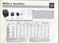
Many were displaced by copper oxide rectifiers in a different circuit. CuO rectifiers don't have much of an inverse voltage rating tho.
And soon replaced by Copper-Sulphide Rectifiers. These were used with the first alternators in police cars & taxi's.
All those tubes & the likes of 10, 50 & so on were designed from the ground up to run their filaments on constant voltage supplies.
I'm familiar with the CC cct many on DIY are using. If the tube involved has a small filament there is definite possibility
of PS leakage across the filament PS assembly is enough to create an interfering voltage that results in noise in the audio.
We don't need to know any of this to build a vacuum tube audio amplifier. But hey, the information is free, so why not. 😀
👍
Attachments
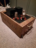
How about this simple single-end KT88. Video series on the design and how to make from start to finish on the Blue Glow YouTube page or from links on the Blue Glow web page. Good looking project. On my amp bucket list.
Attachments

How about this simple single-end KT88. Video series on the design and how to make from start to finish on the Blue Glow YouTube page or from links on the Blue Glow web page. Good looking project. On my amp bucket list.
Have you read the title of this thread?
Thanks for that.Covered in great detail in another thread.
Many here will be using Rod Coleman regs for the filaments. I had a chance yesterday to compare his V4 design with the latest V9 design. They're both excellent, and I don't know of anything better. The V9 is slightly cleaner and more focussed. It is an audible difference. If you already have V4 installed I wouldn't lose any sleep over it. If it's a new build I'd be inclined to the V9.
https://www.lyrima.co.uk/dhtreg/dhtRegIntro.html
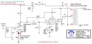
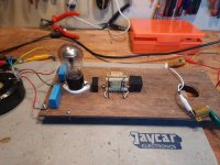
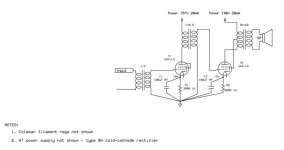
OK - so, not all triodes but all direct heated ... the circuit is 6A4/LA as triode driving 6A4/LA in ultralinear single-ended. Delivers 1 Watt @ 5% THD to 10" full-range drivers.
Not shown in the schematic:
Not shown in the schematic:
- Coleman 6.3V filament regs, or the power transformers, rectifiers and filters feeding them; and
- the HT power supply, in which I used a type BH cold cathode rectifier and C-L-C-R-C filtering (shown on the breadboard).
Attachments
- Home
- Amplifiers
- Tubes / Valves
- All-DHT amplifiers: no indirectly heated signal tubes!