This PSU arose out of a need for compact, low-cost PSU for the FH9HVX.
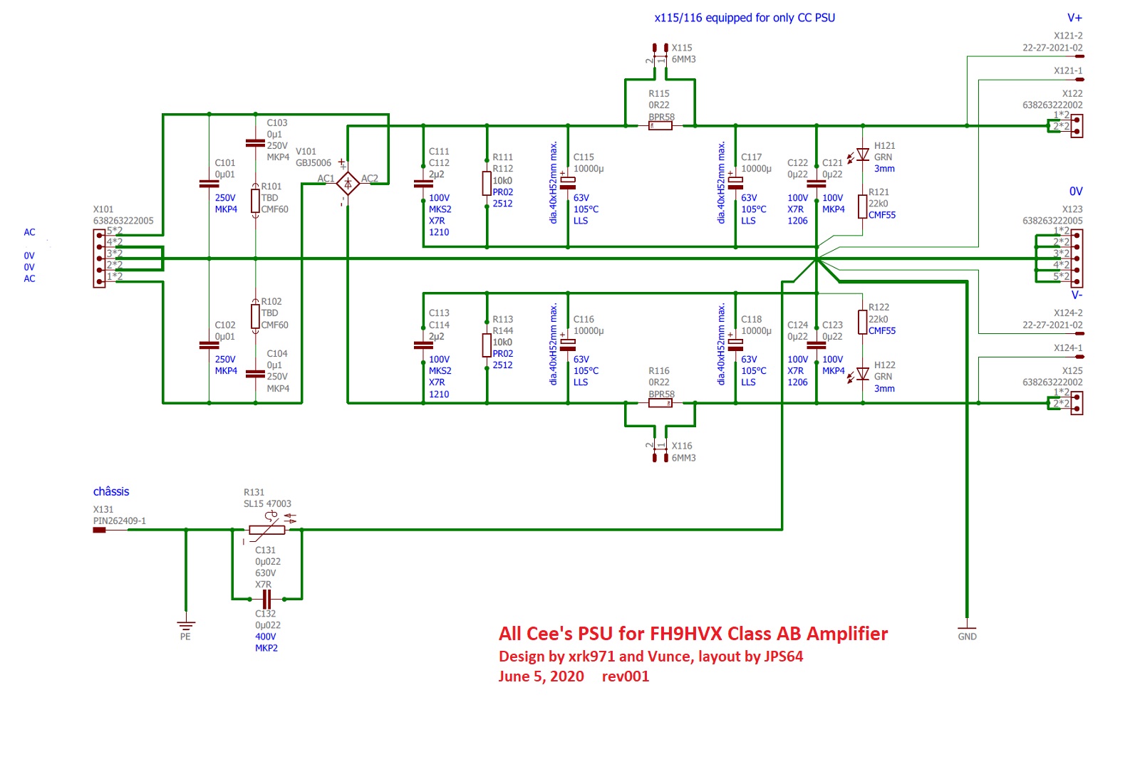
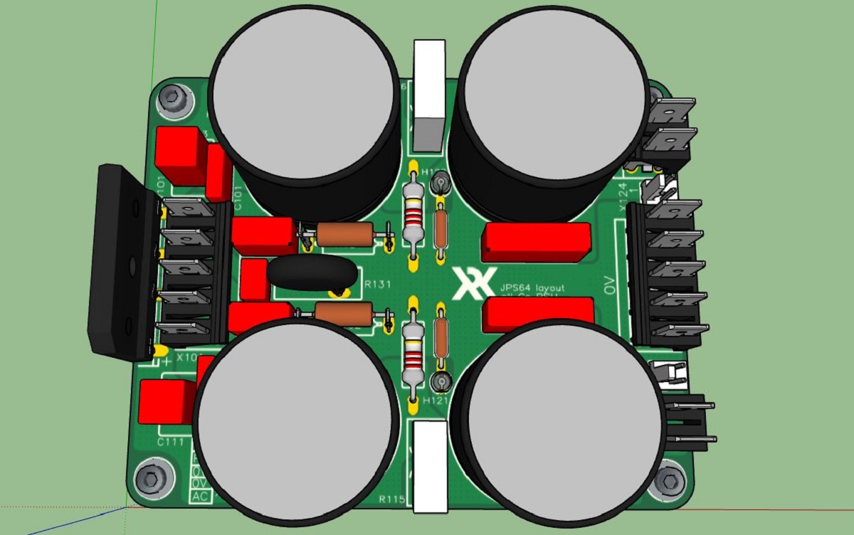
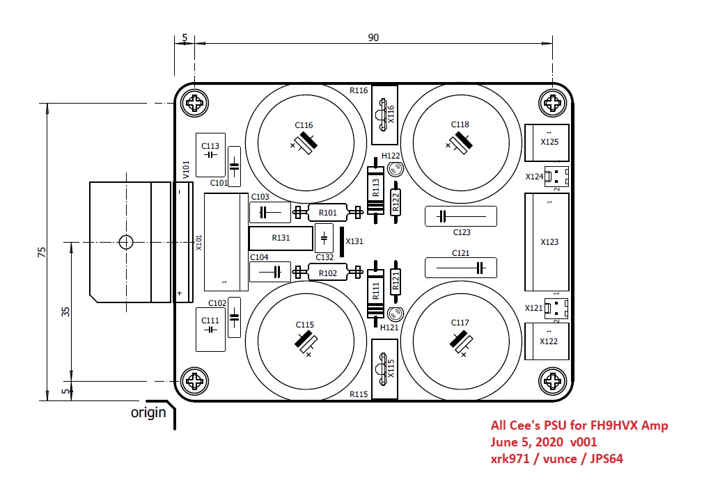
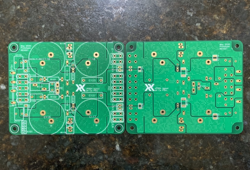
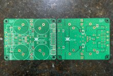
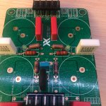
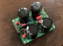
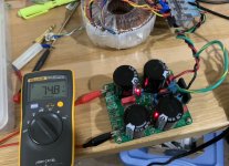
The All Cee's PSU features up to 40,000uF of bulk capacitance at up to 63vwdc. You can install a 0.22R to make it a CRC vs a CC PSU if you desire even lower ripple. Tests show that 20,000uF per rail sounds best in the FH9HVX with no hint of audible hum and a huge reserve for bass impact. Other features include provision for a snubber on the trafo input, bleed resistors, film bypass caps, LED charge indicators, and an on-board NTC ground loop breaker for connection to the chassis/protective earth ground. You can use all Faston tabs or the alternative Wurth 0.250in tab arrays which make it easier to install and keep aligned. All of this is a compact 80mm x 100mm package that will be easy install inside your chassis. If you are running your FH9HVX below 50v rails, you have enough room to install 15,000uF caps for even better performance. The caps in the BOM have been selected for the high ripple current to enable continuous higher power operation if needed. For higher power operation, it is advised to mount the bridge underhung and bolted to a metal floor plate for heatsinking.
Errata Jan 8, 2021: note that maximum diameter of main bulk caps is 30mm, not 40mm as stated on the schematic. 30mm dia snap in caps fit there best.
This PSU is available in my shop for $20.
BOM here:
https://www.diyaudio.com/forums/att...00w-class-ab-lean-times-cees-psu-bom-v001-zip
Shopping cart for BOM here:
FH9HVX - Budget Conscious 100w Class AB for Lean Times
Thank you to JPS64 for another super layout!
Attachments
Last edited:
I might try it as a CLC supply with inductors in stead of R115, R116. What value of inductance would you recommend?
You would need an inductor with pretty low DCR circa 0.22ohm and high current circa 15A or more. I don’t know if anything would fit there unless you did flying leads. I would go for at least 10uH and more is better. Depends on what you are trying to filter. If 50Hz it will be huge. But RF then reasonably sized.
For example, an LC filter with 50Hz cutoff for 10,000uF is 1mH.
For example, an LC filter with 50Hz cutoff for 10,000uF is 1mH.
Last edited:
Note: The BOM linked above uses LLS1J103MELC capacitors w/ a 35mm diam. Looks like the board designed for a 30mm capacitor. LLS1J103MELB or LKS1J103MESB seems like a good replacement. (general purpose vs audio caps, shouldn't provide give a difference for input smoothing)
Last edited:
Yes, board layout is indeed 30mm dia caps with 10mm lead spacing. Sorry about the BOM error. General purpose is fine as this is a PSU bulk cap.
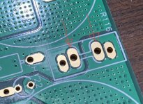
Small error on X116 pads
Hi folks,
We just discovered a small error on the board at X115, the location for the jumper to turn the board from a CRC into an “All Cee’s” board. The pads for X116 meant for a Faston tab are orphaned. That is, they lack the spiders to connect them to the surrounding copper pours. There is a simple fix, use the nearby pads for R116 or use a solder blob to bridge pads from R116 to X116.

Sorry about the mistake - and hope it’s not too big of a problem.
Thanks for your understanding.
Hi folks,
We just discovered a small error on the board at X115, the location for the jumper to turn the board from a CRC into an “All Cee’s” board. The pads for X116 meant for a Faston tab are orphaned. That is, they lack the spiders to connect them to the surrounding copper pours. There is a simple fix, use the nearby pads for R116 or use a solder blob to bridge pads from R116 to X116.
Sorry about the mistake - and hope it’s not too big of a problem.
Thanks for your understanding.
Attachments
Last edited:
How on earth did that mistake circumvent KiCad's error reporting? Pads on footprints are connected to signal nets on the schematic, and the PCB layout editor continuously compares the schematic to the layout. If they're not identical, it screams.
There's also a Design Rule Check feature in the PCB layout editor, with a "List Unconnected Nets" pushbutton. How is it possible for this error to go unreported?
There's also a Design Rule Check feature in the PCB layout editor, with a "List Unconnected Nets" pushbutton. How is it possible for this error to go unreported?
Was wrapping up a bunch of work and got back to this. Just wanted to confirm that the P/N RN60D2202FB14 22KOhm is correct for R121 & R122 and wasn't rolled over from the wrong BOM. Part looked too big and wanted to check it with you guys.
An externally hosted image should be here but it was not working when we last tested it.
(not soldered, just placed)Attachments
Last edited:
If your going to use 10mm standoffs when mounting the board, you could install R121/122 under the pcb. You’ll have a bit more space to bend the resistor leads without the LED right next door.
Sorry about that. The BOM has the wrong wattage there. That’s just the LED resistor. I don’t think it needs to be that big. Just use a smaller 22k 1/4 w axial if you think the fit is difficult.
How can other KiCad users, recognize the problem which occurred on these boards? In retrospect was there any "signature" which hinted, before PCB manufacturing, "hey this is not gonna work" ?
The board was made using Eagle. But there are various third party packages used for post processing the manufacturing files. JPS64 will have to clarify.
Wow, the schematic in post #1 sure looks like KiCad.
So how do other diyAudio members who design their own PCBs, learn from this mistake? What could they do in the future, to prevent this type of mistake from happening on their boards? I hope you don't say it's inevitable, this type of error is unavoidable and undetectable and unpreventable.
So how do other diyAudio members who design their own PCBs, learn from this mistake? What could they do in the future, to prevent this type of mistake from happening on their boards? I hope you don't say it's inevitable, this type of error is unavoidable and undetectable and unpreventable.
Hi X,
Ran into a snag building up the All C's. I have soldered all comp's except the 10Kuf caps. This includes R115 & R116. I purchased 35mm Nichicon snap ins, and they will not fit. The schematic tells me the max should be 40mm. I have tried to force the caps in, but gave that up.
I am not sure if I desoldered C101, C102, R115, R116 and soldered on the bottom of pcb, whether I would even have enough room. The 35mm caps butt up against R115, R116, and the green leds (bending leads), butt up against X122 & X125, and butt up against C101 & C102 .
If I get 2 of the caps in, there is no way to get the other 2 mounted. May have to resort to building up the old CRC's I have laying around, as I really do not want to order 8 more caps to fit the All C's.
Need some ideas if you guys have any.
Thanks,
Myles
Hi Myles,
Sorry about your situation. Where does it say the max diameter is 40mm? Because I need to fix that. It’s 30mm max diameter snap-in caps. 35mm caps will not for there. You could perhaps bend the legs of the nearby film caps to move them away from the bulk caps.
Sorry about your situation. Where does it say the max diameter is 40mm? Because I need to fix that. It’s 30mm max diameter snap-in caps. 35mm caps will not for there. You could perhaps bend the legs of the nearby film caps to move them away from the bulk caps.
Hi X,
On the schematic, it shows in vertical writing, see attached. I do not think I have enough room as I have tried to bend and force quite a bit already. I will look again.
I will be using a 36VAC transformer. If I can get away with 50V caps and if they are smaller, I may have some that I can use or If 50V caps are good for the Xmas amp, I could use it there also?
Myles

Further update X,
Tried everything to get them to fit. No Luck. I tried a dry fit with the other All C's pcb I have and still no luck, bangs up against the header, no matter which way the header is inserted, and still would require leads to be bent and/or components to be lifted/leads bent to make it work.
I have 8 x 6800uf x 50V caps that would fit real nice. Do you think 27,200 uf per board would satisfy the requirements for the Xmas amp (based on 25VAC transformer). If so I can use this as a work around and order a couple of more All C's boards for the FH9HV. Will still have to order smaller caps for the FH9HV though.
Myles
- Home
- Group Buys
- All Cee's PSU for Class AB Amp