Concepts in the making...
Ha, Ha - we are not done yet! Given the volume of these cabinets are well above the total VAS of the drivers - I could add A LOT more larger pieces. 😀
You did hit the nail on the head, I was mainly thinking of braking up the parallel planes. Yet - dare I go deeper to hit the larger wavelegths?!?
And before I move on to cabinet volume, Thank You for the wiring info. I will thank Fluid for investing the time into this discovery. I would have never guessed the series/parallel wiring sequence would have made a difference. I will definitely do parallel banks in series.
Now, about the volume choice I made.
10 years ago, when I was first playing around with the NSB drivers, I tried them in an Open baffle (similar panel size to the panel I used in the drivers blowouts on this thread) and a closed box with the same volume as VAS. The Qts was published at 0.76, so at the time, that seemed logical, as I did not have the DSP or knowledge I have now. At that time, I always preferred the more lively mid-range of the open baffle, but did not like the bass roll-off...
So six years ago, when I came back to these to try as arrays, I did not want to rise the Q too much, so I went large and leaky - way too large. I wanted to create that open baffle mid-range I liked. Also, I did not want to cut the wood into a bunch of useless parts either, in case the whole idea bombed...
I was an array skeptic at one time too. 🙄
...But instead, I enjoyed the build up to January 2017 and gave them the name: Cheap the Cheerful.
So when considering the rebuild, I did contemplate bringing the cabinet size down to VAS. I looked at what others did with these speakers also. Some of the ported designs where about as big as what I had, but I really do not care for ported designs. Then there was the part inside me that said "What if You do all this work, and the sound does not improve and the only path forward is new drivers?" Also, I like the mid-range, why chance changing it?
So, what I decided to do, was make the cabinet 2/3 smaller. Without the braces and diffusion parts, that puts this cabinet at double VAS (still pretty big). (Original was triple VAS). But it does make the Volume about right, just in case I ditch or wear out the NSBs, I could populate these same cabinets with Fostex FF105wk or Markaudio CHN-70. I know this is not the best decision in regards to the NSBs having some power handling protection, but oddly enough, I did not have any issues with the original either. 😉
Also it keeps the experiment pretty interesting - given both cabinets are/were pretty over-sized...
Of course if any of You think this is truly a bad idea (remember the Qts of 0.76) then I can add more bracing and diffusion. 😀 I know I can DSP the Q peak flat, but am skeptical in regards to that being the ideal for the mid-range...
Drawings:
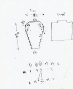
The first one was keeping the cabinet size the same, but having a rounded front and taped back.
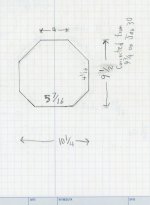
The second one I have had in mind for years, as I mentioned in my "welcome back" post, I have always wanted try a column shaped cabinet. That method of assembly did not work with the pieces of wood I was reusing...
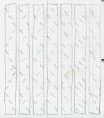
...so I designed it to work with the pieces I was using: third drawing.
The fourth drawing shows different possibilities I was considering with the re-used door trim scraps.
It remains debatable if it really scatters and diffracts inside waves (due to the size compared to wave lengths) but it does a good job of making wall shapes random and brakes up parallel planes.
Ha, Ha - we are not done yet! Given the volume of these cabinets are well above the total VAS of the drivers - I could add A LOT more larger pieces. 😀
You did hit the nail on the head, I was mainly thinking of braking up the parallel planes. Yet - dare I go deeper to hit the larger wavelegths?!?
And before I move on to cabinet volume, Thank You for the wiring info. I will thank Fluid for investing the time into this discovery. I would have never guessed the series/parallel wiring sequence would have made a difference. I will definitely do parallel banks in series.
Now, about the volume choice I made.
10 years ago, when I was first playing around with the NSB drivers, I tried them in an Open baffle (similar panel size to the panel I used in the drivers blowouts on this thread) and a closed box with the same volume as VAS. The Qts was published at 0.76, so at the time, that seemed logical, as I did not have the DSP or knowledge I have now. At that time, I always preferred the more lively mid-range of the open baffle, but did not like the bass roll-off...
So six years ago, when I came back to these to try as arrays, I did not want to rise the Q too much, so I went large and leaky - way too large. I wanted to create that open baffle mid-range I liked. Also, I did not want to cut the wood into a bunch of useless parts either, in case the whole idea bombed...
I was an array skeptic at one time too. 🙄
...But instead, I enjoyed the build up to January 2017 and gave them the name: Cheap the Cheerful.
So when considering the rebuild, I did contemplate bringing the cabinet size down to VAS. I looked at what others did with these speakers also. Some of the ported designs where about as big as what I had, but I really do not care for ported designs. Then there was the part inside me that said "What if You do all this work, and the sound does not improve and the only path forward is new drivers?" Also, I like the mid-range, why chance changing it?
So, what I decided to do, was make the cabinet 2/3 smaller. Without the braces and diffusion parts, that puts this cabinet at double VAS (still pretty big). (Original was triple VAS). But it does make the Volume about right, just in case I ditch or wear out the NSBs, I could populate these same cabinets with Fostex FF105wk or Markaudio CHN-70. I know this is not the best decision in regards to the NSBs having some power handling protection, but oddly enough, I did not have any issues with the original either. 😉
Also it keeps the experiment pretty interesting - given both cabinets are/were pretty over-sized...
Of course if any of You think this is truly a bad idea (remember the Qts of 0.76) then I can add more bracing and diffusion. 😀 I know I can DSP the Q peak flat, but am skeptical in regards to that being the ideal for the mid-range...
Drawings:
The first one was keeping the cabinet size the same, but having a rounded front and taped back.
The second one I have had in mind for years, as I mentioned in my "welcome back" post, I have always wanted try a column shaped cabinet. That method of assembly did not work with the pieces of wood I was reusing...
...so I designed it to work with the pieces I was using: third drawing.
The fourth drawing shows different possibilities I was considering with the re-used door trim scraps.
Attachments

Last edited:
I second look...
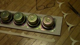
Just got up and saw some of my NSBs on the table and re-remembered that they take up a fair amount of space. With all the bracing, diffusion and drivers (which are going to be fully mounted inside the cabinet) - I am probability closer to VAS then I think. Without going thru some crazy math to figure it out, I would still say I am over, but not near as much as I think.
I am curious to what your guys thoughts are - continue as is, or dial it in to VAS? (I will find a way to figure it out if need be )
)
I designed this stuff so long ago, even I forgot what I was trying to do. 😱
...Or it changed with the creative process. 😀
Just got up and saw some of my NSBs on the table and re-remembered that they take up a fair amount of space. With all the bracing, diffusion and drivers (which are going to be fully mounted inside the cabinet) - I am probability closer to VAS then I think. Without going thru some crazy math to figure it out, I would still say I am over, but not near as much as I think.
I am curious to what your guys thoughts are - continue as is, or dial it in to VAS? (I will find a way to figure it out if need be
)I designed this stuff so long ago, even I forgot what I was trying to do. 😱
...Or it changed with the creative process. 😀
Attachments
Last edited:
Wow, You have peeked some curiosity! I have always wondered what SE brings to the table. Is the gray modu chassis behind the amp modules a part of the design? I see trannys with the modules, so I am thinking those are the PSUs?
The Modushop (DIYA Store Dissipante 4U w/ UMS) holds the smaller brother Alpha 20w amp. The Big Boy is open frame out front and are monoblocks (each with own power cord and PSU with 400VA trafo). The amp dissipates 200w/ch all the time as it is Class A, but there are no temps above 38C due to the very efficient (and quiet) fan-cooled CPU heatpipe coolers. The grey cabinet holds these modules:
Here is how it measures:
Check it out when you get a chance...
Last edited:
I am curious to what your guys thoughts are - continue as is, or dial it in to VAS? (I will find a way to figure it out if need be
I would not be so concerned with the chamber volume and Vas mismatch, as you can tune a lot by adding more dense stuffing (rock wool or fiberglass), or even volume filler like bricks that will add stability and take up space. It has to do more with making sure it handles power well but if too big, will give appearance of "deeper" bass. You are going to use DSP and EQ anf FIR etc etc anyway so it can be driven and controlled at will.
Oh yeah - these:
Here is a link to some impluse graphs I found when I was contemplating my box volume. The post references the source, which I feel pretty confident about:
http://www.diyaudio.com/forums/subwoofers/8114-subwoofer-qtc-tightness.html#post88711
Here is a link to some impluse graphs I found when I was contemplating my box volume. The post references the source, which I feel pretty confident about:
http://www.diyaudio.com/forums/subwoofers/8114-subwoofer-qtc-tightness.html#post88711
Vas on the TC9 I use is 1.19 litre. My chambers are ~ 2.2 L. I would error on the large side. This isn't comparable to OB, as the array effect will se a raise in frequency all trough the midrange. Something you will have to counter with EQ/FIR.
If you haven't seen it yet, this should be required reading: Infinite Line Source: analysis
Damping the chamber is very important. Leaving breathing room around the drivers but also preventing the little wiggles in the impedance plot, which are internal reflections. Once you get that right, the midrange has huge potential, it's definitely one of the strong points of arrays done well.
Sure it depends slightly on the driver used etc. but the EQ is what determines your final tonal balance. Well that, and the fact you'll get the driver you use back on steroids.
What happened with your driver tests? I see you mentioning a couple here.
Edit, just saw the post about impulse... With EQ and FIR, that as well as the house curve is going to determine how the STEP looks.

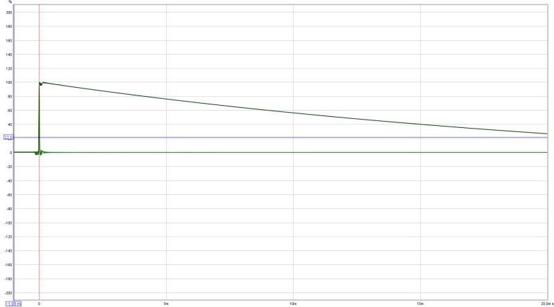
Here is the impulse and step. That step flies high to about 6-7 ms because it extends all the way to ~35 Hz.
The shape of that STEP is determined by the house curve I have set up.
Going with a flat target would look more like this:

This was a linear phase correction with a flat target. See how the STEP extends all the way above zero way past 10 ms?
This is because it is a broad band signal, with linear phase. This was my first eureka moment on the way to time coherency.
Let's see how a DAC looks:
Different scale used here, flying high past 30 ms. This is getting closer and closer to linear output all the way to DC.
That first STEP I showed follows minimum phase for the band passed frequency response I have and is further shaped
by the room curve.
The shape is why they call it STEP response. If it went all the way down to DC you'd see a line from zero straight up to 100% and it would stay there.
The graphs shown there say more about the frequency response and timing than anything else. The IR is the same information as in the frequency response graphs, just presented differently. Almost all of the graphs within REW are linked that way.
So don't sweat it, leave it (the enclosure) big enough and damp it properly. Then EQ to taste.
If you haven't seen it yet, this should be required reading: Infinite Line Source: analysis
Damping the chamber is very important. Leaving breathing room around the drivers but also preventing the little wiggles in the impedance plot, which are internal reflections. Once you get that right, the midrange has huge potential, it's definitely one of the strong points of arrays done well.
Sure it depends slightly on the driver used etc. but the EQ is what determines your final tonal balance. Well that, and the fact you'll get the driver you use back on steroids.
What happened with your driver tests? I see you mentioning a couple here.
Edit, just saw the post about impulse... With EQ and FIR, that as well as the house curve is going to determine how the STEP looks.
Here is the impulse and step. That step flies high to about 6-7 ms because it extends all the way to ~35 Hz.
The shape of that STEP is determined by the house curve I have set up.
Going with a flat target would look more like this:
This was a linear phase correction with a flat target. See how the STEP extends all the way above zero way past 10 ms?
This is because it is a broad band signal, with linear phase. This was my first eureka moment on the way to time coherency.
Let's see how a DAC looks:
Different scale used here, flying high past 30 ms. This is getting closer and closer to linear output all the way to DC.
That first STEP I showed follows minimum phase for the band passed frequency response I have and is further shaped
by the room curve.
The shape is why they call it STEP response. If it went all the way down to DC you'd see a line from zero straight up to 100% and it would stay there.
The graphs shown there say more about the frequency response and timing than anything else. The IR is the same information as in the frequency response graphs, just presented differently. Almost all of the graphs within REW are linked that way.
So don't sweat it, leave it (the enclosure) big enough and damp it properly. Then EQ to taste.
Last edited:
What happened with your driver tests? I see you mentioning a couple here.
Unfortunately, I have not done anything with the Vifa, Fostex or 10F. 🙁
I still plan to revisit that when the inspiration hits...
I mentioned above that it was ten years ago when I played with the NSBs - well, I just double checked my journal - it was closer to 15 years ago! 😱 I did not have a digital camera back then, internet at home, or a measuring system. 🙂 So I am taking the impressions I had back then with a grain of salt, because it was all "by ear" and subjective. And I can guarantee You that the cabinet build back then was not properly damped and not double checked with an impedance plot...
...But based on your last post, and X's, I looks like I am on the right track keeping what I got - I will give that "Infinite Line Source" a read, as I have not read that one yet. 😉
Weird, X's post did not show up, until after I posted #305?... Thanks, X - looks like I am on the right track.
By the way - how do you get the images in the posts? I tried inserting the chart in post #305, but ended up with "click image..." which does not work. I tried copying "copy image address" and "copy link address" using the "insert image" icon...
Last edited:
You mean like this?
Click on image to open it, right click on image and chose properties, copy the address and place it between the image tags. (At least on Windows it works like this)
Same works for pictures you upload to your posts. I have most of my pictures hosted on my private server. That way I still have 'some' control over them.
Do read that thread 🙂. The math may be a bit much to chew on, but it's a good read even if you skip that part.
Last edited:
The fault in your picture upload was:
http://http//www.diyaudio.com/forums/attachments/subwoofers/4497d1038550363-subwoofer-qtc-tightness-step-response-closed-box-gif
See the double "http//" there?
http://http//www.diyaudio.com/forums/attachments/subwoofers/4497d1038550363-subwoofer-qtc-tightness-step-response-closed-box-gif
See the double "http//" there?
Last edited:
See the double "http//" there?
Thanks for that, and Thanks for fixing the image in post #305 above.
I hope others see this post, because I think a lot of others do the same thing if they just paste the link in the box...
I read thru page #1 of Werewolf's thread and I was lost at "eingenfunctions", but thankfully, found my way back by the bottom of the page. I have to read the posts a couple of times as my mind thinks more in terms of shapes, colors, patterns and feelings then it does math. Yet, it is a good testimony to Werewolf's writing ability, because I do eventually understand it. I will just need to take it in slow. 😉
I am also still taking in the graphs in post #306. Possibly leading up to a "Eureka" moment for me, but has not fully clicked, we will be coming back to this when I have more time to write. I am off to bed, as Thankfully, tomorrow (or later today for people with normal daytime work schedules), is the last long work day of the week... 😀
Maybe reading this will help you get some grip on it: Measuring Loudspeakers, Part Two Page 2 | Stereophile.com
See that perfect STEP?
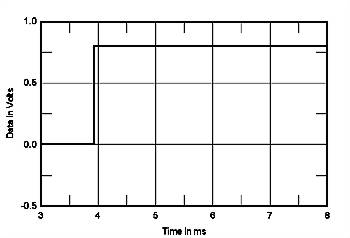
Only 'perfect' in theory, not in our audio hobby. But that's where the name comes from.
See that perfect STEP?
Only 'perfect' in theory, not in our audio hobby. But that's where the name comes from.
...That way its pretty easy to wire it all up in parallel...
Good option - consistently.
And on the powerful, current, tube triode amplifier. With direct exit.
Without the transformer and capacitors.
No gradual slopes in my speakers...
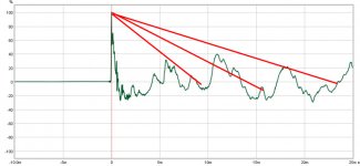
Now I get it, at least the goal we are shooting for: a gradual slope heading down towards zero - like the hypotenuse of a triangle, with a slight concave curve to it. Your graphs illustrate that really well. (Mine don't). It appears that the lower the frequency the system can produce, the more gradual the slope is, taking longer milliseconds to reach zero. If our systems could go down in frequency infinitely, we would get the perfect STEP posted above...
It figures 😉 Good so far?
Now what about this:
As this slope is frequency based, is it safe to say that the frequencies between 0 - 0.5 ms are higher frequencies, 0.5 - 5 ms are mid-range frequencies, and after 5 ms are lower frequencies? I do not expect that I have these "ranges" exact, but that is the general concept, yes? As lower frequencies are longer wavelengths, they would take more time to decay. I am on the right track, yes?
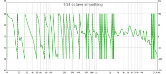
Either way, it looks like I have a lot of work ahead of me. I do not see any gradual slopes in my current Avebury set-up. 😱 I see a lot of phase shifts:
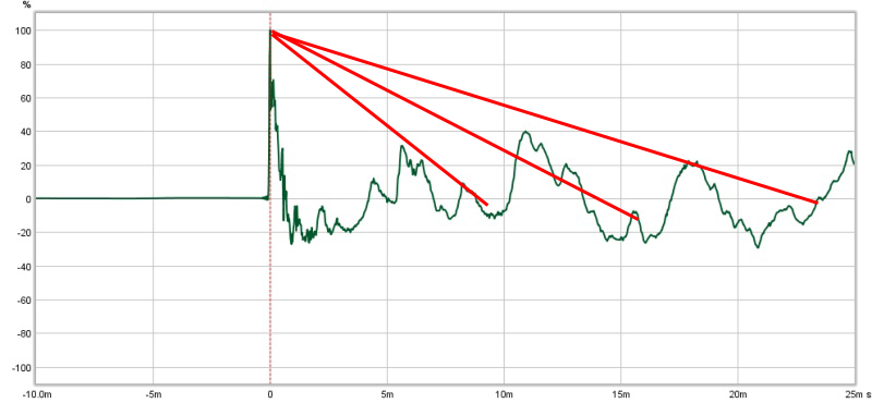
Yet, there ARE a lot of phase shifts - at least at the listening seat. Actually, it is an ongoing downward slope that happens to do many 180 degree cycles. I need to remeasure the speaker itself, but I am guessing a lot of this is room. 😱

It is going to be interesting to see what the column shaped cabinet I am building will do to these slopes. 😀
P.S. A follow-up on image insertion: Right click then select "copy link address" puts the images in the post at full size. "Copy image address" puts them in small.
Measuring Loudspeakers, Part Two Page 2
Now I get it, at least the goal we are shooting for: a gradual slope heading down towards zero - like the hypotenuse of a triangle, with a slight concave curve to it. Your graphs illustrate that really well. (Mine don't). It appears that the lower the frequency the system can produce, the more gradual the slope is, taking longer milliseconds to reach zero. If our systems could go down in frequency infinitely, we would get the perfect STEP posted above...
Only 'perfect' in theory, not in our audio hobby
It figures 😉 Good so far?
Now what about this:
As this slope is frequency based, is it safe to say that the frequencies between 0 - 0.5 ms are higher frequencies, 0.5 - 5 ms are mid-range frequencies, and after 5 ms are lower frequencies? I do not expect that I have these "ranges" exact, but that is the general concept, yes? As lower frequencies are longer wavelengths, they would take more time to decay. I am on the right track, yes?
Either way, it looks like I have a lot of work ahead of me. I do not see any gradual slopes in my current Avebury set-up. 😱 I see a lot of phase shifts:
Yet, there ARE a lot of phase shifts - at least at the listening seat. Actually, it is an ongoing downward slope that happens to do many 180 degree cycles. I need to remeasure the speaker itself, but I am guessing a lot of this is room. 😱
It is going to be interesting to see what the column shaped cabinet I am building will do to these slopes. 😀
P.S. A follow-up on image insertion: Right click then select "copy link address" puts the images in the post at full size. "Copy image address" puts them in small.
Attachments
Last edited:
You've got the right idea here, but as always, there is more to it. Every little thing that upsets either frequency response or time (or both) is going to change how the IR and STEP is going to look.
So a room curve changes the overall STEP shape. As does a crossover, as that changes time. But measuring at the listening position also includes reflections. Which is what you see with that rotating phase.
This is a reason for me to use the frequency dependent window to took at FR/phase. The window will be longer and longer the lower the frequency gets. So reflections happening a little later in time (say 6 ms) do not show up at higher frequencies and we can see the phase shape of that first wave front.
Another thing that helps is acoustical treatment of first reflections, the further you bring them down, the less influence they have on the frequency response and it's timing.
You can't fix these things with DSP, as that would hold true in only one spot. However once the room is sufficiently treated and your speaker concept allows for it, DSP can work over a larger area. That's where I see the array having an advantage. Move up, move down, move left or right and the shape will hold up.
A single driver can do much of the same but does reflect on floor and ceiling. Treat it and any DSP thrown at it will hold up over a larger area.
While most people will simply assume I use DSP to get the in-room response in check, I actually try and use it as much as I can to tweak the speaker only. There is no escaping the room of course. So you do need to verify every step of the way.
- Status
- Not open for further replies.
- Home
- Loudspeakers
- Full Range
- All Aspiring Full-Range Array project